Signal Definitions
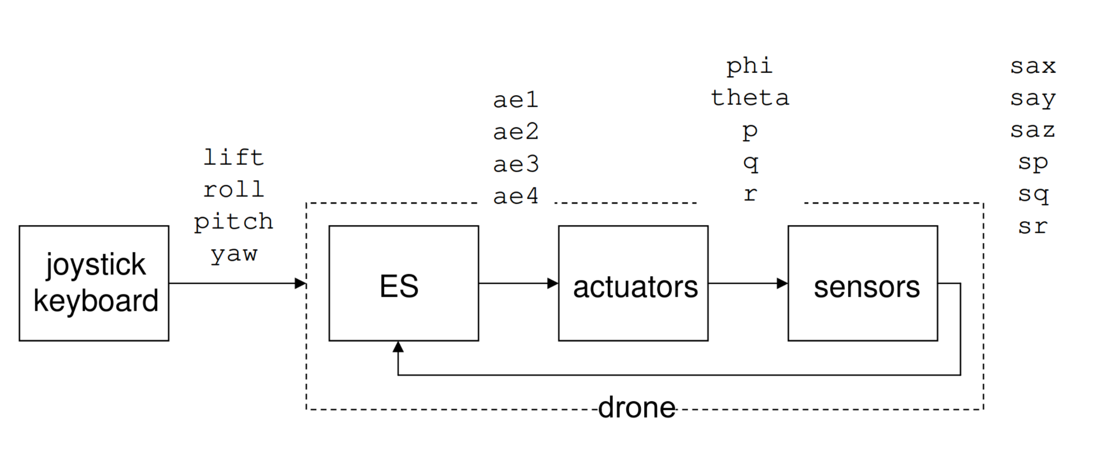
In the interest of clarity and standardization, in following we define some of the most important signal names as to be used in the project. We refer to the generic system circuit shown in Figure 1:

The four most important signals originating from joystick or keyboard are called:
lift(engine RPM, keyboard: a/z, joystick: throttle)roll(roll, keyboard: left/right arrows, joystick: handle left/right (x))pitch(pitch, keyboard: up/down arrows, joystick: handle forward/backward (y))yaw(yaw, keyboard: q/w, joystick: twist handle)
The actuator (servo) signals to be sent to the drone electronics are called
ae1(rotor 1 RPM)ae2(rotor 2 RPM)ae3(rotor 3 RPM)ae4(rotor 4 RPM)
The sensor signals received from the drone electronics are called
sp(p angular rate gyro sensor output)sq(q angular rate gyro sensor output)sr(r angular rate gyro sensor output)sax(ax x-axis accelerometer sensor output)say(ay y-axis accelerometer sensor output)saz(az z-axis accelerometer sensor output)
Note that the sensor signals sax, sp etc. do not equal the actual drone angle and angular velocity θ,p etc.
as defined earlier. Just like other drone state variables such as x, y, z, u, v, w, etc., they cannot be directly
measured (unfortunately), which is why the sensors are there in the first place. Rather, the sensor signals are
an (approximate!) indication of the real drone state, and proper determination (recovery) of this state are an
important part of the embedded system. For simulation purposes [4], where the true drone state variables are
obviously available (i.e., simulated), the drone state variables are called
x,y,zphi,theta,psi(φ, θ, ψ)X,Y,ZL,M,Nu,v,wp,q,r
which implies that these names must be used when referring to these signals in the Rust code.