UAV Theory Of Operation
In the figure below, we describe the variables that are standard terminology in describing aerial vehicles location and attitude (NASA airplane standard).

We use two coordinate frames, the earth frame and the (drone) body frame. When the drone (body frame) is fully 3D aligned with the earth frame, both x axes are pointing in the direction of the drone’s flight direction. The y axes are pointing to the right, while the z axes are pointing downward. The variables are defined as follows:
x,y,z: coordinates of the drone CG (center of gravity) relative to the earth frame [m]φ,θ,ψ: drone attitude (body frame attitude) relative to the earth frame (Euler angles) [rad]X,Y,Z: forces on the drone relative to the body frame [N]L,M,N: moments on the drone relative to the body frame [N m]u,v,w: drone velocities relative to the body frame [m s−1]p,q,r: drone angular velocities relative to the body frame [rad s−1]
The forces X, Y, Z result in (3D) acceleration of the vehicle, while the moments L, M, N result in rotation
(change in roll, pitch, yaw). In hover, Z determines altitude (to be controlled by lift), while L, M, N need to
be controlled by roll, pitch, and yaw, as explained later on.
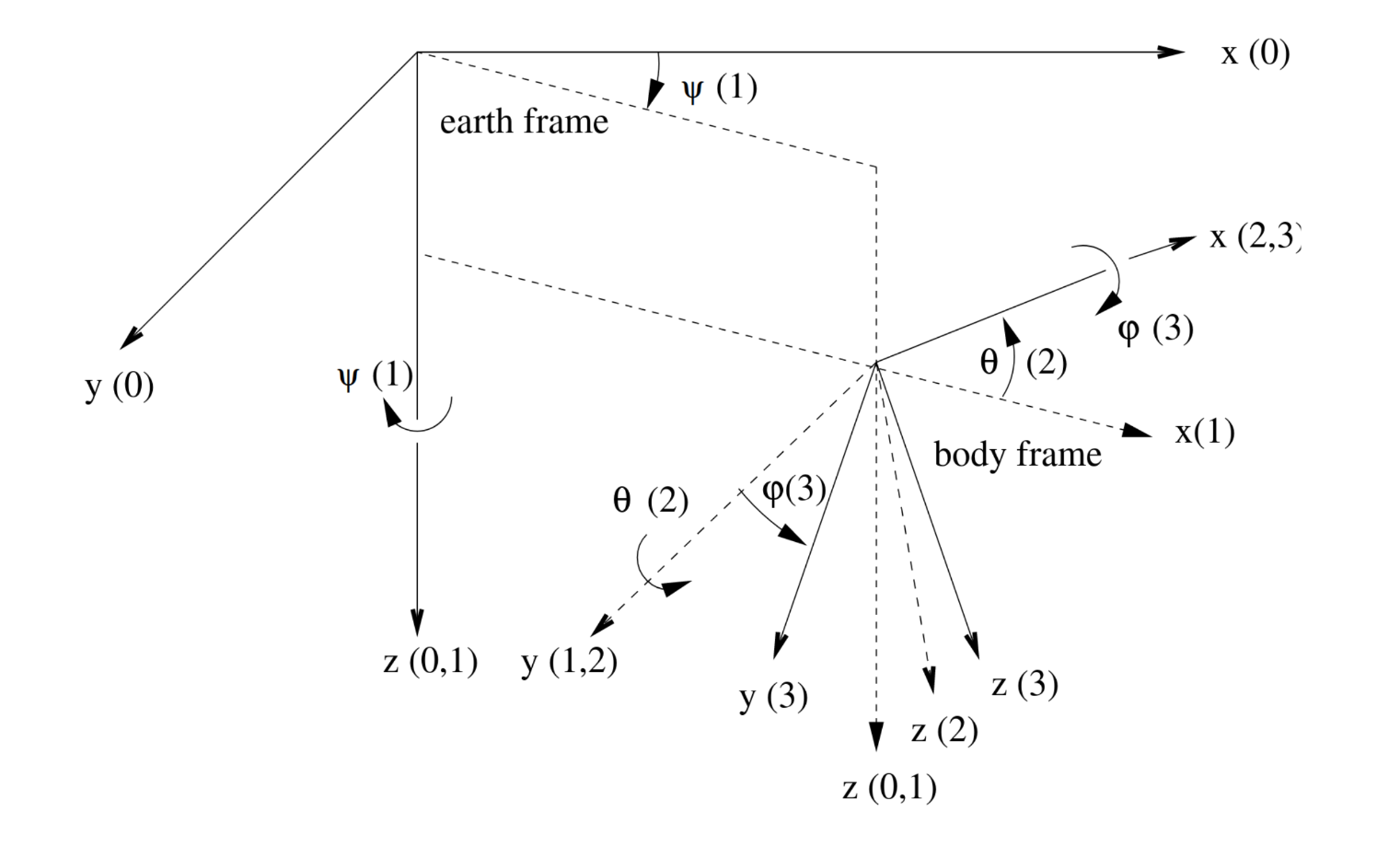
The Euler angles φ, θ, and ψ are not included in the above Figure, as their graphical definition is less trivial. They
describe the attitude of the body frame relative to the earth frame, and are defined in terms of three successive
rotations of the body frame by the angles ψ, θ, φ, respectively1. Before applying the rotations the body frame is
fully aligned with the earth frame. First, the body frame is rotated around the z axis (body frame, earth frame)
by an angle ψ. Next, the body frame is rotated around the y axis (body frame) by an angle θ. Finally, the
body frame is rotated around the x axis (body frame) by an angle φ.
Note, that the order of rotations (ψ, θ, φ) is significant as different rotation orders will produce a different
final body frame attitude. The Euler angle definition is shown in the image below, where the index (i) denotes the
various body frames in the course of rotation (0 initial body frame, 3 final body frame).

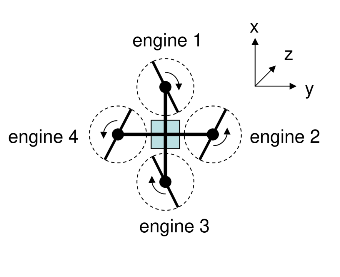
The forces X, Y, Z and moments L, M, N are applied externally through gravity, and the four rotors. The above forces and moments are given by
X = 0
Y = 0
Z =
L =
M =
N =
where denote rotor RPM, and and are drone-specific constants. The above equations directly follow from the rotational direction of the rotors as shown in the image below:

The rotor RPM is approximately proportional to the voltage applied to the engines, which, in turn, is proportional to the duty cycle of the PWM signals generated by the drone interface electronics, which are controlled by (actuator engine i).
Note that refers to incorrect terminology, as
estands for engine, while the drone’s rotors are driven by motors. Switching terminology would be a major undertaking as all developed reference code and documentation refers to these labels, so theeshould be interpreted as electrical motor.
As a result, the above equations can also be directly expressed in terms of the actuator signals to according to
X = 0
Y = 0
Z =
L =
M =
N =
where b′ and d′ are drone-specific constants. Note, that in order to compute the to produce a desired lift
(through ), roll (through ), pitch (through ), and/or yaw (through ), the above system of equations
must, of course, be inverted.
The other variables u, v, w and p, q, r are governed by the standard dynamical and kinematic equations that
govern movement and rotation of a body in space [3].
-
In drone and helicopter terminology, the three rotations are known as yaw, pitch, and roll, respectively, and are referred to as heading, attitude, and bank in airplane terminology. ↩