Development kit
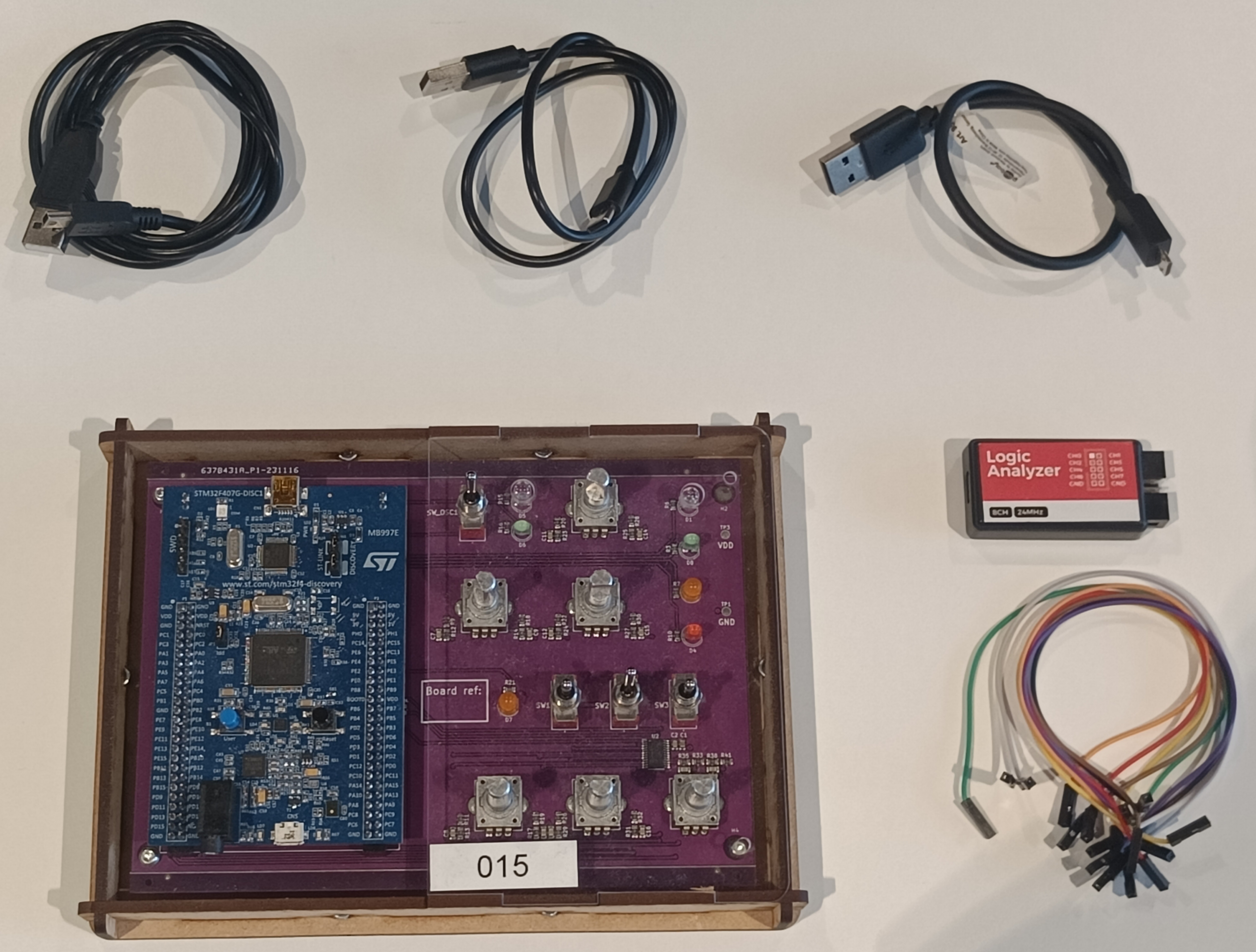
All the work that you will be doing for the labs require you to use the provided hardware. Once you have picked up the hardware in Lab 1, ensure that you have all the components listed below and shown in the dropdown image.
- STM32F407 Discovery Board + Daughter Board
- USB-A to USB-mini cable
- USB-A to USB-micro cable
- USB-A to USB-C cable
- Logic Analyzer
- Jumper cables
STM32F407 Development Board
The main development board using in this lab is the STM32F407DISCOVERY by STMicroelectronics. It uses the STM32F407VGT6 microcontroller which is a 32-bit Arm Cortex-M4 microcontroller with FPU. It also has some additional features like an on-board embedded debug tool, an audio DAC with integrated class D speaker driver, LEDs and push-buttons. Most of these additional features will be used in these labs.
More information about the board can be found at: STM32F407DISCOVERY.
Some usefull documents for the Development Board:
Custom Daughter Board

For the labs you are also provided with an custom daughter board to be used along with the STM Dev board. The daughter board adds a variety of IOs which are used in both assignment A and B. The additional IOs are:
- 5 GPIO LEDs (D1/D3/D4/D7/D8)
- 6 Rotary Encoders (S1/S2/S3/S4/S5/S6)
- 3 Single Pole Double Throw (SPDT) Toggle Switches (SW1/SW2/SW3)
- 1 SPDT Touggle Switch with LEDs (SW_OSC1 & D5/D6)
The LEDs and the toggle switches are connected to the dev board using on-board GPIOs. The Rotary encoders are connected to the board using and IO Expander chip (PCA9555PW). This chips is connected to the dev board through I2C protocol. The connections are presented in the below image:

You can also take a look at the schematic for the daughter board here.