Synthesizer Hardware
Synthesizer electronics
The synthesizer electronics consist of two main components (see Figure 2). The first is a development board with a microcontroller which is used to host the Zephyr OS and the synthesizer application code. This microcontroller is mounted onto the second main component, a printed circuit board (PCB) containing switches, encoders, and LEDs which you can use to interact with the synthesizer. We will refer to this PCB as the peripherals board.

Figure 4: the synthesizer board.
You can find the electrical schematic of the synthesizer here. This resource is provided in case you are interested in how it has been implemented, but you don't need it for the assignment. As you will have access to the physical board, you can also see where each of the components in this schematic are located on the board.
If you don't come from an electrical background, you can also find simple guides on how to read datasheets on the internet like this one. This example is a nice one to get started.
Synthesizer interface
You can print information from the synthesizer on your computer by using the micro USB serial port located at the bottom of the development board (CN5). Additionally, you can play notes by pressing keys on your keyboard and sending this information through the serial console. Refer to the lab setup if you don't know how to use a serial console. In Figure 3, you can see the keyboard mapping.
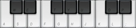
Figure 3: Computer keyboard layout. Credits to peachpit.com
If you are not familiar with music notes, don't worry - you are not required to play any meaningful melody or chord. For the whole assignment, you don't need any music proficiency :). However, if you are curious, you can see the corresponding musical notes in Figure 4:

Figure 4: Keyboard notes. Credits to smackmypitchup.com
To be able to continuously play notes with your synthesizer, we recommend using a terminal-like serial monitor like minicom, screen, or picocom that constantly sends your keyboard inputs to the development board. For an enjoyable user experience, the use of the Arduino or Microsoft Serial monitors is discouraged.
Synthesizer configuration
You saw the peripherals board that you will be using in Figure 2. The top half of the board is comprised of 6 LEDs (D1, D2, D4-D7), a switch (SW1) and three encoders (ROT1-3) that are mostly related to sound generation. The bottom half of the board, containing an LED (D3), three switches (SW2-4), and three encoders (ROT4-6), is dedicated to sound shaping. Below you will find a description of how the synthesizer is configured using these peripheral components. However, if you don't care, just toggle SW1 out of its neutral position and, if you press a valid key in your keyboard, you should hear sound produced. To get a basic view of the different building blocks of a synthesizer, we recommend reading this introductory article.
If you just want to produce a basic sound, switch up the top switch and when you press a valid key a sound should play. To get a basic view of the different building blocks of a synthesizer, we recommend reading this introductory article. Our synthesizer is divided into two parts. The top part controls the two oscillators, which are responsible for the sound generation as well as the master volume and the low-pass filter. The bottom part controls the modulators and the special effects. Below you can find information about each feature.
Top Half
This synthesizer has two oscillators which are selected by toggling the top switch out of its neutral position. D5 lights up to indicate that you are selecting oscillator 1, while D6 lights up to indicate that you are selecting oscillator 2. ROT1 controls the the waveshape of the oscillator; you can select between square, sine, triangle and sawtooth. You should see a message on the console each time you change the waveshape. ROT2 controls the amplitude/volume of the selected oscillator while ROT3 selects its frequency/pitch. The oscillators can be configured and used simultaneously. To use both oscillators, it suffices to select the first oscillator, raise its amplitude, and then select the second oscillator and raise its amplitude.
When the top switch is in its neutral position (in the middle position, when no LED is on), ROT2 controls the general volume of the composite sound (the combined sound produced by oscillator 1 and 2). Additionally, with the top switch in this state, you can also control a low pass filter (pending feature). ROT1 sets the cutoff frequency for the filter, while ROT3 adjusts the filter's resonance frequency. The table below summarizes all these configurations:
| Top switch | Encoder 1 | Encoder 2 | Encoder 3 |
|---|---|---|---|
| Up: Oscillator 1 | Waveform | Pitch | Volume |
| Down: Oscillator 2 | Waveform | Pitch | Volume |
| Neutral | LPF resonance (pending feature) | LPF cutoff frequency (pending feature) | Global volume |
Bottom Half
Now let's move to the lower half of the board. SW2 selects between different effects that can modify the sound outputted by the synthesizer. If it is switched up, you are selecting the low-frequency oscillators (LFOs) Modulators (LFOM). If it is switched down, you are selecting the Amplitude Modulators (AM). These are not yet implemented, but if you like the project, you can contribute to the project. When the switch is in its neutral position, we are considering adding special effects like phasers, delays or distortion. Again, you are free to implement new features and contribute to the project.
The parameters of the LFO modulation are set with 2 out of the 3 bottom encoders. ROT4 sets the amplitude of the LFOs, while ROT5 sets their frequency. For now, ROT6 is not used since it will only configure the amplitude modulators. The amplitude modulation parameters can be set with the 3 bottom encoders. We follow the classical ADSR (Attack, Decay, Sustain and Release) envelope. ROT4 sets the Attack and the Decay, ROT5 sets the Sustain and ROT6 sets the Release. Amplitude modulation is a pending feature.
SW2 | Encoder 4 | Encoder 5 | Encoder 6 |
|---|---|---|---|
| Up: LFOM | Amplitude | Pitch | None |
| Down: AM | Attack and Decay | Sustain | Release |
| Neutral: TBD | TBD | TBD | TBD |
The LFOs and AM modulate a particular configuration. This is controlled by SW3. Again, all you need to know is here in this introductory article. When SW3 is in its upper position, it modulates the selected effect on Encoder 2 and when SW3 is in its lower position, it modulates the selected effect on Encoder 3. The selected effects are determined by the position of the top switch. If this sound a little bit confusing just try playing around with the knobs, every time you change the position of a switch, you should see information printed with the configuration you selected.
| Top switch | SW3 | Modulation |
|---|---|---|
| Up: Osc 1 | Up | Osc 1 pitch |
| Up: Osc 1 | Down | Osc 1 volume |
| Down: Osc 2 | Up | Osc 2 pitch |
| Down: Osc 2 | Down | Osc 2 volume |
| Neutral | Up | LFP cutoff frequency (pending feature) |
| Neutral | Down | Master volume |
Status LEDs
There are additional LEDs in the upper-right corner of the peripherals board that can provide additional information about the state of the synthesizer. D5 indicates if the processor is currently running: its pulse width is equal to the processor's utilization. D7 indicates if it is currently overloaded. The rest of the LEDs don't have any function yet. We are open for suggestions!
NOTE: in the assignment, you will be asked to implement the toggling of
D7to indicate if the system has been driven into overload.