Logic Analyser Setup
A logic analyser is used to observe which task is executing and to profile your implementation. An additional software needs to be installed to interface with the logic analyser. Most of them like PulseView or Logic2 are compatible with your device. PulseView is licensed under GNU Public License while Logic2 is a free software from the reference Logic Analyzer manufacturer. We recommend you to download Logic2 version 2.4.10. If you are unable to get Logic2 to work, you can use Logic1 as well. You can download PulseView here and Logic2 here.
Logic2 in Linux
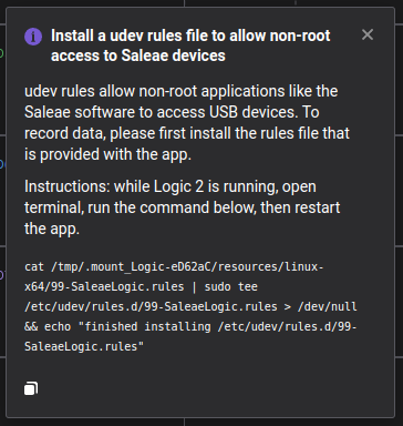
For Linux: Logic2 requires udev rules to be set for the logic analyzer (see Figure 1). In case you missed the prompt, you can run the following:
cat /tmp/.mount_Logic-eD62aC/resources/linux-x64/99-SaleaeLogic.rules
| sudo tee /etc/udev/rules.d/99-SaleaeLogic.rules > /dev/null
&& echo "finished installing /etc/udev/rules.d/99-SaleaeLogic.rules"
Connecting to the Logic Analyser
This step helps you determine if your lab setup works correctly.
Ensure you test your setup in Lab 1 itself, to avoid delays with the assignments.
- Connect the logic analyzer to a USB port using the USB-A to USB-C cable.
- Connect a jumper cable from
GNDon the logic analyzer toGNDon the development board. - Connect jumper cables from
CH0-CH3on the logic analyzer toPD12-PD15on the development board.- Pinout for all the other channels can be found in Development Kit.
- The full configuration connection diagram can be seen in Figure 2.
- Start up Logic2 (or PulseView or Logic1), if the logic analyzer is plugged in, you should see the 8 available channels in the window.
- Build and flash the
Assignment Aproject onto the development board. The program should start running immediately. You can read out the channels from the logic analyzer by pressing the start button in the right upper corner in Logic2. If you see the measurements rising and falling in channels 0, 1 and 2, that means the setup is working correctly.

Logic1 - Coloured traces
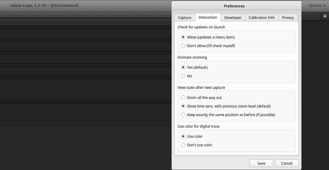
In case PulseView and Logic2 do not work on your machine, you can also use Logic1. The basic version of logic one doesn't use different colours for channels which may make reading the logic analyser outputs difficult. However, it is possible to manually enable coloured channels. This can be done as follows, open the Options menu on the top right corner of the window. Then open the preferences dialog box. This should display a list of check boxes. Check the Use color box under Use color for digital trace then click on save. You should now be able to see traces with colours, which makes distinguishing between which pin each trace corresponds to easier.
Figure 3: Enable coloured traces in Logic1