NOTE: The first lab (Monday, 18/11/2024 08:45-12:30, Flux Hall-C) is mandatory as the hardware required to perform both the assignments will be handed out.
Real-time Systems
This is the homepage for the real-time systems course. You can find most course information here.
This course is part of the CESE masters programme.
This course will teach you about the following topics:
- Basic concepts of real-time systems
- Worst case execution time estimation
- Scheduling policies
- Response-time analysis
- Jitter analysis
- Handling overloads
- Multiprocessor scheduling
- Reservation-based scheduling
Grading
Your grade consists of the following components:
The lab assignments form 40% of the grade. They have to be submitted strictly before the deadline. There is no resit opportunity for the assignments.
| Assignments | Deadline always at 23:59 | Percentage of the labs grade | Percentage of the final grade |
|---|---|---|---|
| A - Programming a scheduler | 7 December 2024 (week 4) | 40% | 16% |
| B - Synthesizer | 18 January 2025 (week 8) | 60% | 24% |
The combined grade of both lab assignments must be higher than a 5.0. There is no minimum grade for each assignment.
Additionally, the course has a final exam. This exam weights 60% of your grade, and it has a resit opportunity. The maximum of the regular and resit exam grade is taken.
| Exams | Date | Time |
|---|---|---|
| Final Exam | 29 January 2025 | 13:30 - 16:30 |
| Resit Exam | TBD | 9:00 - 12:00 |
Labs
Every week (on Monday) there will be lab sessions with TAs. In these lab sessions you can ask questions and discuss problems you are having (including those related to the Toolchain). As you will receive a piece of hardware in the labs in week 2, at least one of the group members has to be there to pick up the hardware. For that purpose, in week 2, you have to give 50€ as a deposit before picking up the hardware. You will get this money back once you bring the hardware back when told to do so. Alternatively, if you are following Embedded Systems Lab (Q3), you can exchange your hardware there. During the course, there will be announcements on Brightspace with all the relevant information.
You should perform the assignments in groups of 2 people. In order to receive the repositories, you have to enroll in a group in Brightspace. To submit your assignments, you just need to commit your solution and your report to the main branch before the deadline. If you don't manage to find a teammate before the first lab (Monday, 18/11/2024 08:45-12:30, Flux Hall-C), we will pair you with someone during the lab.
Fraud Policy
Fraud and aiding to fraud is a serious offense and has the following consequences: (1) being expelled from the course. (2) being reported to the EEMCS Examination Board. All submitted code will be subjected to extensive cross-referencing to check for fraud. Reusing any code or report text from anyone else or from AI tooling such as ChatGPT, GitHub Co-Pilot, etc.. is not allowed. Similarly, making code or text available to other students will have the same consequences.
TAs
The lectures of this course will be given by George Iosifidis and Koen Langendoen.
During the labs you will interact with the TA team:
- Himanshu Savargaonkar
- Shashwath Suresh
- Orhan Yavaşcan
- Fatih Aslan
Contact
If you have doubts about the theory part of the course, you can contact George at G.Iosifidis@tudelft.nl.
If you need to contact the TAs regarding labs, you can find us at the course email address: rts-ewi@tudelft.nl.
Alternatively, if you REALLY need to speak to one of us directly, you can contact Himanshu Savargaonkar at H.Savargaonkar@student.tudelft.nl or Shashwath Suresh at S.Suresh-3@student.tudelft.nl.
Note that we prefer that you use the course email address.
Lab Setup
In order to start working with your Zephyr RTOS and your board, you first need to set up the toolchain you are going to use throughout the labs and configure your IDE to help you develop and debug. We recommend to set it up before the first lab. Bear in mind that you need to download a couple GBs of data, and you will use around 6 GBs of space inside your computer.
The following pages will guide you through the setup
- Toolchain Setup - covers the toolchain setup and other packages needed to do the assignments
- Editor Setup - explains how to set up your IDE for a simpler build, debug and flashing process
- Development kit - an overview of what you the hardware picked up in Lab 1
- Logic Analyser Setup - explains how to install the required software and packages for using the provided logic analysers
Toolchain Setup
The framework you will be using to program the hardware is based on Zephyr, a lightweight open-source real-time operating system (RTOS). It is one of the most widely used open-source RTOS. You will use Zephyr for both assignments. This section will guide you through the Zephyr installation.
The documentation for setting up Zephyr can be found here. We recommend a quick read, even if you are installing it with the Linux script. Linux users can follow the steps in the For Linux users section. Windows and macOS users will have to go through the guide in the For Windows or macOS users section.
Here are a few things to keep in mind when setting up the toolchain. Should you diverge from these recommendations, the support you will receive from the TAs will be limited!
- This assignment has been tested on Windows, Linux (Ubuntu, Fedora and Arch), as well as on macOS Sonoma with Apple Silicon
- We highly recommend using a Linux distribution for these labs.
- While working with Zephyr (and especially on Windows), you might find problems that we haven't encountered. Feel free to ask the TAs for help during the labs; however, we encourage you to give it some tries first independently, keeping in mind that Zephyr enjoys extensive support online.
- Building and flashing takes much longer in Windows.
- Due to issues with executables, Zephyr does not support flashing the applications with WSL.
- For IDEs, we recommend CLion (preferred) or Visual Studio Code as those have been tested with these lab assignments. NOTE: Ensure there are no spaces in file/folder names you create
For Linux users:
-
Download
zephyr-install-ubuntu.zipif you are on Ubuntu orzephyr-install-fedora.zipif you are on Fedora. -
Extract the script inside the zip file. Ubuntu users should now have
zephyr-install-ubuntu.shand Fedora users should havezephyr-install-fedora.sh. -
Run the extraced script, by first opening a new terminal instance in the directory the extracted script is present in and then executing
chmod u+x zephyr-install-ubuntu.shfollowed by./zephyr-install-ubuntu.shif you are on Ubuntu, orchmod u+x zephyr-install-fedora.sh./zephyr-install-fedora.shif you are on Fedora.Note:
- You will be prompted several times during the installation - say "yes" to all.
- If you are on Ubuntu or Fedora the required packages will be installed for you. However, on other distributions you will need to manually install the dependencies mentioned in the installation script (this list is printed on the terminal when the script is run).
- Note that this will create two directories,
zephyrprojectandzephyr-sdk-*, in your home directory which will be required for Assignment A and Assignment B. You can edit the script and change the location of these directories if you want. - Note that this script uses commands from the Getting Started Guide from Zephyr. Essentially it runs all the required commands for you. Check this guide if you want to know in detail what the commands do on your computer.
-
Attach the development board via the USB-A to USB-mini cable.
-
Navigate to the Zephyr installation directory, using the command
cd ~/zephyrproject
- Then activate the virtual environment, using the command
source .venv/bin/activate
Remember to do this every time you are working with Zephyr
- Now compile and upload the blinky program provided by Zephyr using the below commands. After executing it, if you see a blinking LED on the board you have installed Zephyr successfully! You can now continue with Configuring Building and Flashing.
west build -p always -b stm32f4_disco zephyr/samples/basic/blinky
west flash -r openocd
For Windows or macOS users:
-
You need to follow the Getting Started with Zephyr guide.
- Do not forget to change
<your-board-name>withstm32f4_discoin the Build the Blinky Sample section.
- Do not forget to change
-
Once you have the board, you can proceed with the last step of the guide, to Flash the Sample. You should see a blinking LED on the board.
- In order to flash the application, you might need to install a couple of dependencies. If needed:
- for Windows, you can download OpenOCD's pre-built files here, extract it and move it to your desired program location. Then, add it to your system environment's path, you can find here a tutorial on how to update your PATH.
- When you have OpenOCD installed and you get an error related to
libusb_open()not working, you can try installingSTLinkUSB drivers instead. You can find the download page here - for macOS, use the command
brew install open-ocd.
- You might also need
elftools, used to parse ELF files. In such a case, you can execute this command:pip install pyelftools.
- In order to flash the application, you might need to install a couple of dependencies. If needed:
-
If you see a blinking LED on the board you have installed Zephyr successfully! You can now continue with Configuring Building and Flashing
Configuring Building and Flashing
Once you have successfully installed the toolchain on either Linux or Windows and have tested the setup with the sample program, you will configure west, which is Zephyr's multi-purpose tool which we will use for building and flashing the assignments.
Follow the next steps:
-
Clone your assignment's repository.
-
Next, execute the following command in your Zephyr installation directory:
west build -p always -b stm32f4_disco <<<path/to/assignment>>>
If building fails, we suggest you take a look at some of the tips in the troubleshooting guide.
- After the previous command you can build your assignment source code using
west buildand upload/flash/burn your assignment to the board by runningwest flash -r openocd.
IMPORTANT
- You have to run these commands in your Zephyr installation directory and not your assignment directory! .
- Remember that each time you want to use
westyou have to activate the virtual environment by executing in your Zephyr installation directory the commandsource ./.venv/bin/activatefor Linux. For Windows, it depends on the shell you are using, refer to the Zephyr documentation.
The process of building and flashing is considerably easier when using an IDE. To know more about how to set up your IDE for the assignments, take a look at editor setup. However, before you setup your IDE, ensure that you have installed a serial monitor, check this section for details on how to install a serial monitor and connect to the board console.
Using a Debugger
Zephyr allows for debugging in gdb. The development board includes an onboard debugger. After building the project, you can debug by typing west debug and a gdb prompt should appear. Be aware that you will need to debug with the command line.
When answering questions for the assignment, be sure to run your code using
west flashrather thanwest debug.
Next to gdb you can debug via the console in both assignments. This requires a serial connection from your computer to the micro-USB port on the development board. As opposed to directly debugging with gdb, you have to connect the computer to an additional USB port located on the board.
Connecting to the board console
Physical connections
You should have a spare USB-A to USB-micro. You use this cable to communicate with the microcontroller by connecting it to the bottom connector of the development board. You should end up with something similar to the image below:
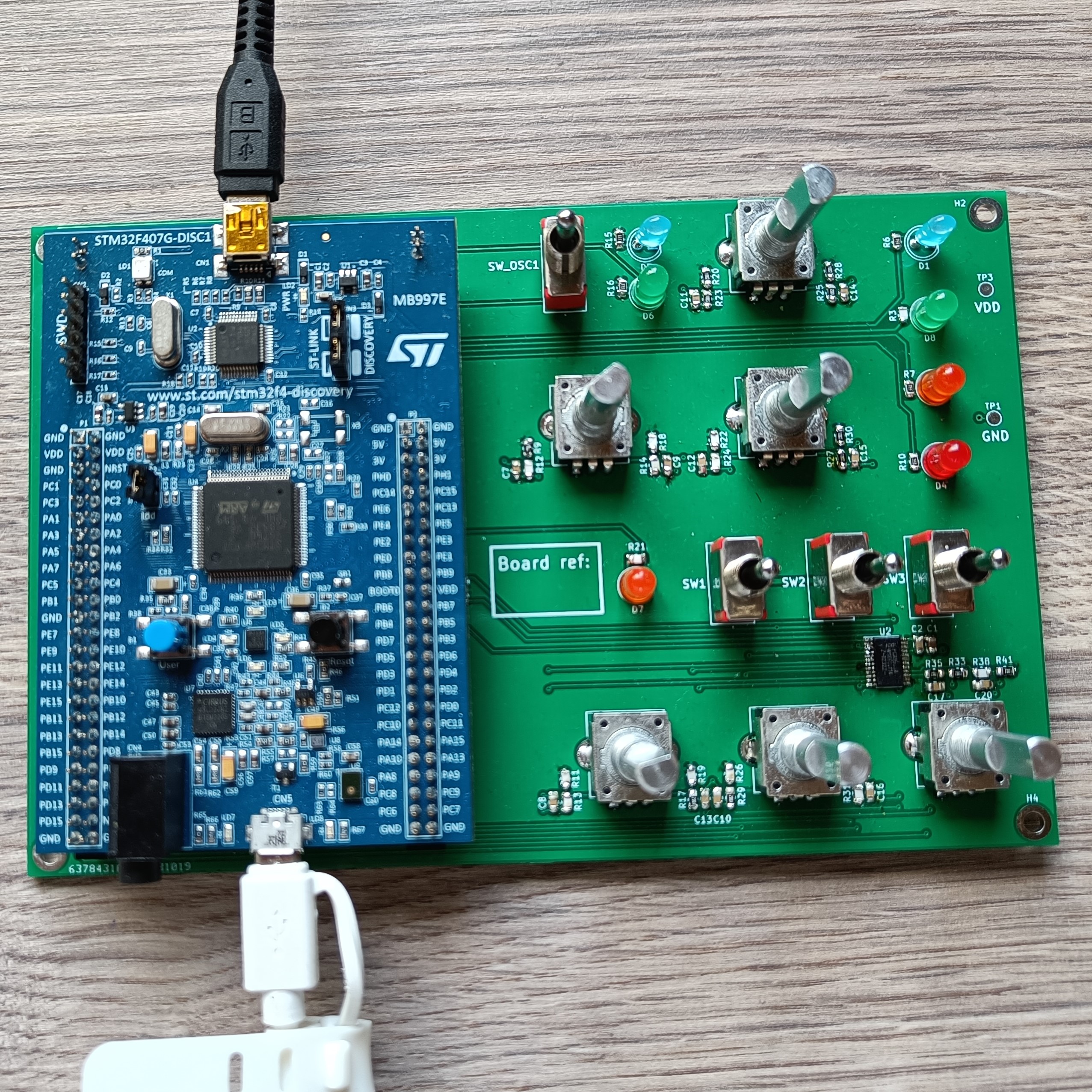 Figure 6: Assignment B setup
Serial Monitor
You also need to install a serial monitor. If you are using Linux, you can install screen, minicom or picocom. All of them are command line based. If it is the first time you are connecting to a serial port, you might have to add yourself to the dialout group. You can do it by executing the following command:
sudo adduser <<<user>>> dialout
If you are using Windows, you cannot use the aforementioned applications. VS Code has an extension from Microsoft, Serial Monitor, that we strongly recommend, even for Linux users, and Arduino has also a serial monitor that you might be familiar with. There are standalone applications like Serial Lab that can also do the job.
After you have cloned Assignment A repo, open main.c and uncomment the macro CONSOLE_ENABLED. Then build and flash the code to the board. Remember that if it is the first time building the project, you have to execute the whole build command, otherwise, you can just execute west flash to compile and build, or west build to just build.
Then, a new serial port should appear in your computer's list of devices, Device Manager for Windows and /dev for Linux. You can then connect to the board with the default baudrate, 115200. Soon after, you should see "Initialization finished!" pop up on your screen.
Editor Setup
As suggested in the main setup, you are free to use any editor of your choice. However, we recommend using CLion or Visual Studio Code, as we have set up guides that have been verified and tested for these two IDEs.
Refer to the CLion guide or the Visual Studio Code guide, based on whichever editor you choose to use.
Make sure you complete setting up your editor before Lab 1, so you can verify the toolchain set up as soon as you get your hardware
CLion
CLion being an IDE, offers a simpler and more intuitive way of building, flashing and debugging applications. Building and flashing can be done in a single click, without having to activate the virtual every time you wish to use west and debugging is much simpler, as breakpoints can be set using the GUI and the values of variables can also be viewed through the GUI. Actions like step are also much easier to execute through the GUI. The only downside to using CLion is that it is heavier than a few popular IDEs and editors.
To use CLion for building, flashing and debugging, a CMake profile and Run/Debug using OpenOCD must be configured correctly. This guide, based on the one published by Zephyr, but modified for our board (stm32f4_disco), walks you through the setup procedure.
Required plug-ins
Make sure you have installed the CMake plugin for CLion before moving to the configuration.
Getting started
Clone your assignment repository and open it as a CLion project, to get started with the setup.
Note, this is a project specific set-up, so for each new project (Assignment B, or a new checkout of your repo), you will have to repeat these steps.
For the CMake configuration, Windows users should follow CLion CMake setup for Windows users and Linux (all distributions) should follow the CLion CMake setup for Linux users.
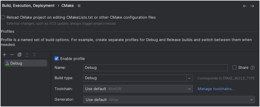
CMake Profile - Windows
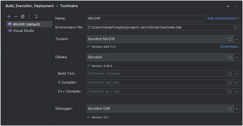
The first step is to create a CMake profile. If you are opening a repo for the first time, then CLion may open this window for you. If it doesn't open automatically, open the CLion settings wizard and navigate to the CMake submenu, under the Build, Execution and Deployment menu. Then clock on Add profile. Then click on Manage toolchains
Then click on Add environment and enter the path to your zephyrproject folder, followed by \.venv\Scripts\activate.bat. Ensure you use the bundled CMake and MinGW tool-set. Then click on apply.
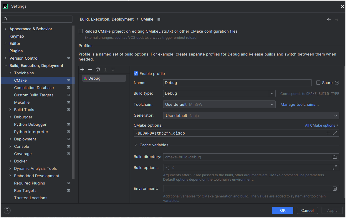
You should now be redirected to the CMake Profile window in Figure 1. Add the following option to CMake options: -DBOARD=stm32f4_disco. Then click on apply and close the window. If the configuration was done correctly, you can see that the CMake execution finishes successfully (in the CMake terminal in CLion) and a cmake-build-debug folder is created.
New CMake Profile - Linux
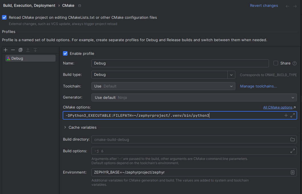
The first step is to create a CMake profile. If you are opening a repo for the first time, then CLion may open this window for you. If it doesn't open automatically, open the CLion settings wizard and navigate to the CMake submenu, under the Build, Execution and Deployment menu. Under this menu, click on Add Profile. Then, add the following CMake option - -DPython3_EXECUTABLE:FILEPATH=~/zephyrproject/.venv/bin/python3.
The final configuration should resemble the screenshot below:
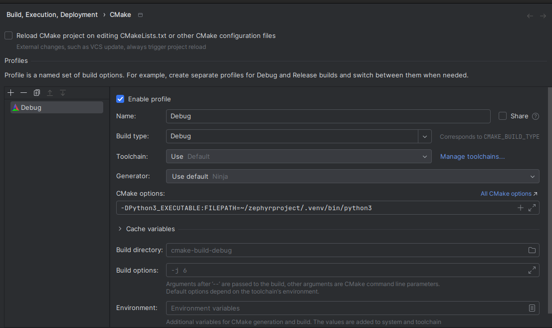
This concludes the CMake profile setup, if all the steps were followed correctly, a CMake build should have been triggered (can be seen in the CMake window). Furthermore, if the CMake build was successful, a new cmake-build-debug directory must have been created in the project directory.
Note: The next section is common for both Windows and Linux users
Run/Debug configurations
The next and final step is to correctly set up the Run/Debug configurations so the board can be flashed and the onboard debugger can be used for debugging through CLion.
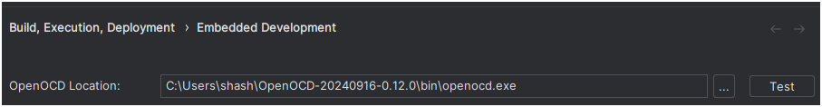
First, make sure that your OpenOCD location is set correctly. This can be found under Settings -> Build, Execution and Deployment > Embedded Development.
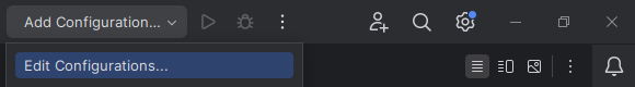
In order to do so, the Edit Configurations wizard under Add Configuration... needs to be used. This can be found in the CLion title bar. (Refer to the screenshot below)
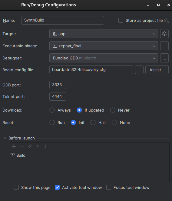
Once the wizard launches, use the + icon to add a new OpenOCD Download & Run configuration. Set the Target to app and Board to board/stm32f4discovery.cfg.
The configuration should look like this:
If all the steps have been followed correctly, then the run and debug icons (right hand side of the title bar) should now be green, like in the image below:
Note the Run/Debug configuration name may differ, as this is user defined
Building, flashing and debugging can now be done using these icons. Clicking on any of them should show that the building and flashing/debugging steps are being executed in the terminal.
VS Code
This is a new guide and may contain inaccuracies, if you find any incorrect information or have ideas for a more streamlined process, you are encouraged to share them with the TAs so we can update these instructions accordingly
VSCode is a much lighter IDE than CLion and is an excellent choice for those looking for a lightweight IDE which allows a large degree of freedom when it comes to customizations. VSCode also has a lot of useful extensions that can make it easier to use and write better quality code. Like with other IDEs, it is possible to build and flash with a single click, without having to activate the virtual environment every time you wish to use west and debugging is much simpler, as breakpoints can be set through the IDe and the values of variables can also be viewed through the GUI. This guide is similar to this Zephyr VS Code example, which can be used as reference to modify and/or add additional functionality.
Note: A lot of commands and paths are OS and PC specific, so it is best you understand what each task does. Simply copy pasting the templates will not work!
Required Extensions
Make sure the following VSCode extensions are installed prior before going to the next steps.
- C/C++
- CMake Tools
- Cortex-Debug
Setting up compile comands and configuring C/C++ extensions
You can follow Zephyr's guide to set up linting and navigation. Once you do this, you should be able to navigate to header files and syntax highlighting should no longer give incorrect errors and/or warnings.
Flashing using OpenOCD
We can configure a task in task.json (should be created inside the .vscode directory) that builds the application code and then flashes the board using OpenOCD. To do this, first create a new tasks.json file and then use the template below (use the one corresponding to your OS!) to configure a task that can build and flash the application onto the board.
Linux
{
    "label": "Build & Flash using West", // Feel free to give it any label you like
    "type": "shell",
    // Remember to update paths so they match your zephyr installation and your assignment
    "command": "cd ~/zephyrproject && source ./.venv/bin/activate && west build -p always -b stm32f4_disco <<replace with path to assignment repo>> && west flash -r openocd && deactivate",
    "group": {
        "kind": "build",
        "isDefault": true
      },
},
Windows
{
    "label": "Build Zephyr Project with West and Flash with OpenOCD",// Feel free to give it any label you like
    "type": "shell",
    "command": "cmd.exe",
    "args": [
    "/c",
    // Remember to update paths so they match your zephyr installation and your assignment
    "cd zephyrproject && .\\.venv\\Scripts\\activate && west build -p always -b stm32f4_disco <<replace with path to assignment repo>> && west flash -r openocd"
    ],
    "problemMatcher": [],
    "group": {
    "kind": "build",
    "isDefault": true
    },
},
Once configured, you can run it using the shortcut Ctrl+Shift+B.
Debug using OpenOCD and Cortex Debug
VS Code can also be used for debugging with OpenOCD and GDB.
In order to debug using the IDE, a new launch configuration has to be defined that launches the gdb debugger and indicates to it the OpenOCD server to connect to. At the same time a new task has to be created that launches OpenOCD debug server for GDB to connect to.
The first step is the configuration for gdb. We use cortex-debug for this and a template to configure can be seen below (the configuration should be placed in .vscode/launch.json):
{
    "version": "0.2.0",
    "configurations": [
        {
            "name": "Debug",
            "type": "cortex-debug",
            "cwd": "<<if you used the script, then your home directory>>/zephyrproject", //We will launch GDB from the Zephyr project directory - path to your Zephyr installation here
            "executable":  "./zephyr/build/zephyr/zephyr.elf", //Path to executable
            "request": "launch",
            "servertype": "external", //External server - we launch OpenOCD separately
            /// On Windows, look for `arm-none-eabi-gdb.exe`
            "gdbPath": "/usr/bin/arm-none-eabi-gdb", //Replace with the path to GDB on your PC!, if you don't have GDB, you will have to install it!
            "gdbTarget": "localhost:3333",
            "preLaunchTask": "openocd" //We ask VSCode to launch OpenOCD (the launch configured as a task) before GDB
        },
    ]
}
The template for the task (to be placed as a separate task inside .vscode/tasks.json) to launch OpenOCD:
{
  "tasks": [
    // Other tasks
    {
        "name": "openocd",
        "type": "shell",
        "command": "/usr/bin/openocd", //Remember to use the correct path to the openocd executable! On Windows, look for `openocd.exe`
        "args": [
            "-f"
            "board/stm32f4discovery.cfg" //Link to the board config file goes here, this is the one in your OpenOCD installation, not from Zephyr!
        ],
        "problemMatcher": [""],
        "isBackground" : true, // We run this in the background, so we will have to remember to close it once we are done using it!
    }
  ]
}
You can also choose to manually launch OpenOCD using the terminal. To do so, start debugging through the GUI or using F5 and then in a new VSCode terminal instance execute the commands corresponding to your OS. Note that you may see a pop-up saying that openocd doesn't exit, click on debug anyway and continue. This is just VSCode reminding us that this task is will continue running in the background and has to be closed manually.
Windows Users
"REPLACE with OpenOCD path" -f "Path to board file here"
Linux Users
/usr/bin/openocd -f "Path to board file here" #Your OpenOCD path may be different!
Development kit
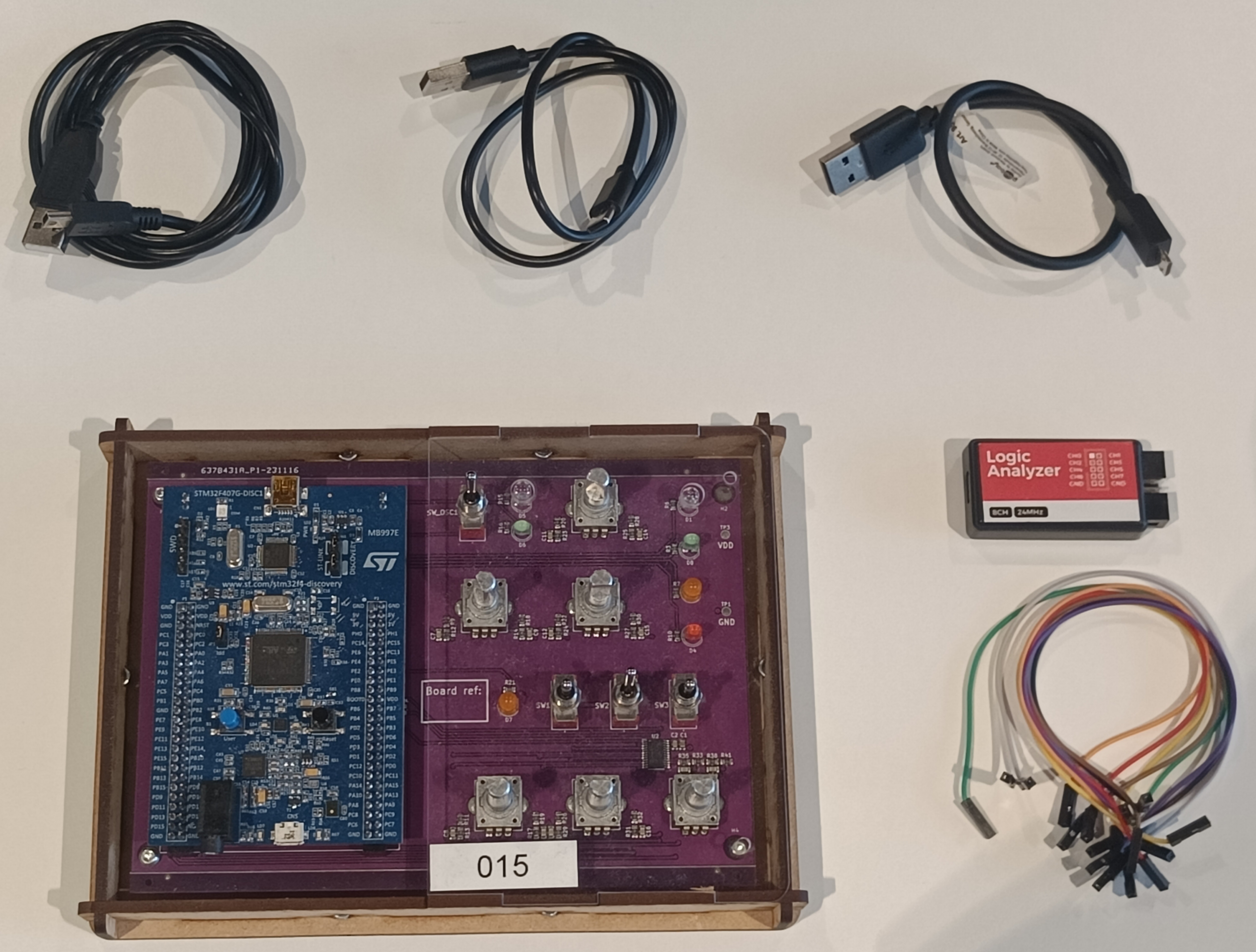
All the work that you will be doing for the labs require you to use the provided hardware. Once you have picked up the hardware in Lab 1, ensure that you have all the components listed below and shown in the dropdown image.
- STM32F407 Discovery Board + Daughter Board
- USB-A to USB-mini cable
- USB-A to USB-micro cable
- USB-A to USB-C cable
- Logic Analyzer
- Jumper cables
STM32F407 Development Board
The main development board using in this lab is the STM32F407DISCOVERY by STMicroelectronics. It uses the STM32F407VGT6 microcontroller which is a 32-bit Arm Cortex-M4 microcontroller with FPU. It also has some additional features like an on-board embedded debug tool, an audio DAC with integrated class D speaker driver, LEDs and push-buttons. Most of these additional features will be used in these labs.
More information about the board can be found at: STM32F407DISCOVERY.
Some usefull documents for the Development Board:
Custom Daughter Board

For the labs you are also provided with an custom daughter board to be used along with the STM Dev board. The daughter board adds a variety of IOs which are used in both assignment A and B. The additional IOs are:
- 5 GPIO LEDs (D1/D3/D4/D7/D8)
- 6 Rotary Encoders (S1/S2/S3/S4/S5/S6)
- 3 Single Pole Double Throw (SPDT) Toggle Switches (SW1/SW2/SW3)
- 1 SPDT Touggle Switch with LEDs (SW_OSC1 & D5/D6)
The LEDs and the toggle switches are connected to the dev board using on-board GPIOs. The Rotary encoders are connected to the board using and IO Expander chip (PCA9555PW). This chips is connected to the dev board through I2C protocol. The connections are presented in the below image:

You can also take a look at the schematic for the daughter board here.
Logic Analyser Setup
A logic analyser is used to observe which task is executing and to profile your implementation. An additional software needs to be installed to interface with the logic analyser. Most of them like PulseView or Logic2 are compatible with your device. PulseView is licensed under GNU Public License while Logic2 is a free software from the reference Logic Analyzer manufacturer. We recommend you to download Logic2 version 2.4.10. If you are unable to get Logic2 to work, you can use Logic1 as well. You can download PulseView here and Logic2 here.
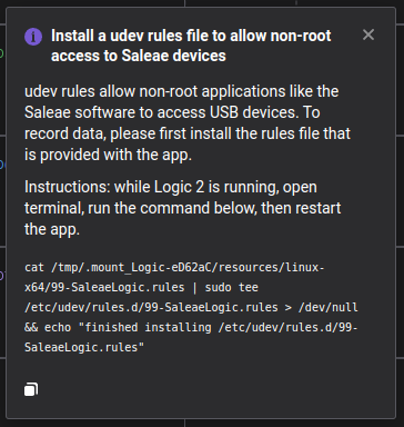
Logic2 in Linux
For Linux: Logic2 requires udev rules to be set for the logic analyzer (see Figure 1). In case you missed the prompt, you can run the following:
cat /tmp/.mount_Logic-eD62aC/resources/linux-x64/99-SaleaeLogic.rules
| sudo tee /etc/udev/rules.d/99-SaleaeLogic.rules > /dev/null
&& echo "finished installing /etc/udev/rules.d/99-SaleaeLogic.rules"
Connecting to the Logic Analyser
This step helps you determine if your lab setup works correctly.
Ensure you test your setup in Lab 1 itself, to avoid delays with the assignments.
- Connect the logic analyzer to a USB port using the USB-A to USB-C cable.
- Connect a jumper cable from
GNDon the logic analyzer toGNDon the development board. - Connect jumper cables from
CH0-CH3on the logic analyzer toPD12-PD15on the development board.- Pinout for all the other channels can be found in Development Kit.
- The full configuration connection diagram can be seen in Figure 2.
- Start up Logic2 (or PulseView or Logic1), if the logic analyzer is plugged in, you should see the 8 available channels in the window.
- Build and flash the
Assignment Aproject onto the development board. The program should start running immediately. You can read out the channels from the logic analyzer by pressing the start button in the right upper corner in Logic2. If you see the measurements rising and falling in channels 0, 1 and 2, that means the setup is working correctly.

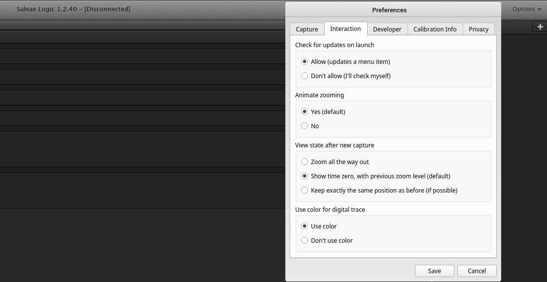
Logic1 - Coloured traces
In case PulseView and Logic2 do not work on your machine, you can also use Logic1. The basic version of logic one doesn't use different colours for channels which may make reading the logic analyser outputs difficult. However, it is possible to manually enable coloured channels. This can be done as follows, open the Options menu on the top right corner of the window. Then open the preferences dialog box. This should display a list of check boxes. Check the Use color box under Use color for digital trace then click on save. You should now be able to see traces with colours, which makes distinguishing between which pin each trace corresponds to easier.
Figure 3: Enable coloured traces in Logic1
Troubleshooting guide
Some of the solutions to common problems students have faced when setting up the toolchain are provided here.
If you have faced other issues that are not here and have managed to solve them, please get in touch with the TAs so this website can be updated and other students facing similar issues can benefit.
CMake unable to find Python or Zephyr
In some cases, CMake fails to find Zephyr and Python. If this is the case on your machine, then add the following to CMakeLists.txt, right after the set(CONF_FILE prj.conf).
find_package(python)
find_package(Zephyr REQUIRED HINTS $ENV{ZEPHYR_BASE})
Note that you have to replace
find_package(Zephyr)withfind_package(Zephyr REQUIRED HINTS $ENV{ZEPHYR_BASE})and not have both
CMake still unable to find Python
If CMake still can't find Python, then add the below to CMakeLists.txt, right after set(CONF_FILE prj.conf).
set(Python3_EXECUTABLE "/usr/bin/python")
set(PYTHON_EXECUTABLE ${Python3_EXECUTABLE})
Assignment A: Coding Schedulers
In this assignment you will be implementing and testing several schedulers for a real-time system on actual hardware (STM32F4DISCOVERY).
You will use Zephyr RTOS to implement RM (rate-monotonic), EDF (earliest-deadline-first) and FP (fixed priority) aperiodic schedulers. RM, EDF and FP servers are scheduling algorithms discussed in the Lecture 5, Lecture 6, and Lecture 9 respectively. In this assignment you will put this theory into practice. The resulting schedules must then be plotted and analyzed by using a logic analyzer.
Learning Objectives
Considering the learning objectives of the course, this assignment (partially) focuses on the following:
- Discuss advantages and disadvantages of different scheduling policies for a given platform or system
- Identify (reverse engineer) parameters of a scheduling scheme or a task set from output traces of the system
- Evaluate the scheduling overheads of a given implementation (in the lab)
- Implement event-based scheduling policies on a given microcontroller (in the lab)
Submission Information
Deadline: 7th December 2024 23:59 (week 4)
The assignment is submitted by pushing to the main branch of this repository.
The last commit before the deadline will be considered your submission.
We recommend frequently committing in order to prevent losing progression. Please note that you cannot directly commit to the main branch. You need to make a merge request between a different branch and main.
The report should be submitted as a .pdf, in the root of the main branch your GitLab repository. Use a maximum of 6 pages for your report (A4, standard font size, single-column, including images). The filename should be formatted as: assignment_a_report_group_X.pdf where X is your group number. Inside the report you should specify your names and student numbers. Use the following template for the report: RTS_assignment-a-template
Following your assignment's submission, the TAs might conduct oral checks about the assignment. For example, you might be asked to change parts of the code or explain the report. There will be a follow up announcement with more information.
Using the console
For this assignment, you can use the built-in Zephyr console and use Zephyr's printk that works exactly the same way as printf from the standard C library. Ensure that printk is not called in a interrupt routine, it can cause unpredicted behaviour.
When you want to debug, you just have to uncomment the CONSOLE_ENABLED macro in main.c. Be aware that initialization will block untill you don't connect the computer to the console.
WARNING: The use of print statements will mess up the scheduling timings. When measuring with the logic analyzer, be sure that you don't call any print statement.
Assignment questions
I. Understanding the System
Let's take a look at the system you will be working with for this assignment. The scheduler functions are found in scheduler.c. It is already set up with a simple
scheduler example and a task set tasks in main.c. New tasks can be added to the schedule by using the spawn_task
function which takes an execution time (ms), period (ms) and a GPIO pin. This task should execute for the given time
every period, during which it sets the pin to high. The available pins are listed in gpio.h.
-
(2 points) Is the
examplescheduler a real-time scheduler? Justify your answer. -
(1 points) Calculate the hyper-period of
TASK_SET_1inmain.c. -
(2 points) Design two new non-trivial task sets with at least 3 tasks with a maximum hyper-period of 120ms.
- One with a processor utilization factor of 1 -
TASK_SET_2 - One with a processor utilization factor over 1 -
TASK_SET_3
Calculate and report the processor utilization factors for both task sets and document these in your report. Note that you will be using these later on in the assignment, so do not make them too difficult.
- One with a processor utilization factor of 1 -
Clarification: Non-trivial task set is a task set where all tasks have an execution time greater than 1 ms, and there are no repeated tasks: tasks with the same period and execution time.
Your main.c should resemble this snippet:
#ifdef TASK_SET_1
   //Task set provided
#elifdef TASK_SET_2
   //Non-trivial task set, U = 1
#elifdef TASK_SET_3
   //Non-trivial task set, U > 1
#elifdef APERIODIC_TASKS
   // Periodic task set provided in question IV
   // Aperiodic tasks you define based on the requirements in question IV
#endif
You can switch which task set is active by changing #define TASK_SET_1 (at the top of the file) to the task set of your choice. I.e. #define TASK_SET_2 for task set 2 and #define TASK_SET_3 for task set 3
Important:
- At any point in time, only one of these defines must be present
- Note that the code supports a maximum of 8 tasks.
II. Implementing a Rate Monotonic Scheduler
In scheduler.c, implement a rate monotonic scheduler in the rate_monotonic function. The scheduling algorithm should
schedule the first pending task with the shortest period.
Some points about helping you implement this:
- To select the scheduler, change the
SchedulerTypeargument passed to therun_scheduler()function. - The
rate_monotonicfunction should select the next task to be executed based on the scheduling algorithm, which in this case is the first pending task with the shortest period, this is done with theset_active_taskfunction. When there are no pending tasks,set_idleneeds to be called. - The
rate_monotonicfunction is invoked when a task is finished or when it has delayed itself. It should delay itself until a higher priority task is ready (preemption of the current running task) or until there is a task ready to be scheduled when there were no tasks running. This delay should be calculated and ak_timeout_tstruct containing the delay time needs to be returned. Learn more about kernel timing here: Kernel Timing. Some of the functions/macros that you might find useful areK_MSEC,K_USEC,sys_timepoint_calc,sys_timepoint_timeoutandk_uptime_get. - For the following questions you are expected to add fields to the
Taskstruct given inscheduler_impl.hin order for you to make a rate monotonic scheduler. - Check the Zephyr kernel API reference for more information. We recommend looking at the pages about the threads and system_clock APIs.
- (12 points) Implement a rate monotonic scheduler in the function
rate_monotonicinscheduler.c. Briefly explain how it works and mention what fields you added to theTaskstruct. Report the output of the logic analyzer for the given task set inmain.c. Verify that the scheduler works correctly. - (4 points) Measure the overhead of your RM scheduler with the given task set in
main.cand calculate the percentage of the hyperperiod that is spent on this overhead. What actions does the scheduler need to do during this time? - (5 points) Explain what overloading is and how your rate monotonic scheduler handles it. Use the given task set in
main.cwith a processor utilization < 1, and the two task sets that you made in question 3 (U = 1 and U > 1). Compare and report how the task sets with their different utilizations (U < 1, U > 1) behave. Now use the task set with U = 1. How does this task set's behaviour differ from what is expected in theory?
Clarification: You dont need to handle over-load just continue running the algorithm. We want you to analyse what happens when the scheduler is over-loaded
III. Implementing an Earliest Deadline First Scheduler
In scheduler.c, implement the earliest deadline first scheduler in the earliest_deadline_first function.
This scheduling algorithm should schedule the first pending task with the earliest nearing deadline.
Similar points about implementing this:
- Change the
schedulefunction to call theearliest_deadline_firstscheduler. The function should perform similar actions as described in therate_monotonicfunction, but it should schedule with the EDF algorithm. - Add necessary fields to the
Taskstruct in order for you to make an earliest deadline first scheduler. - Use the
set_active_taskfunction to select the task to execute. In this case that should be the first pending task with the earliest nearing deadline.
- (10 points) Implement an earliest deadline first scheduler in the function
earliest_deadline_firstinscheduler.c. Briefly explain how it works and mention what fields you added to theTaskstruct. Report the output of the logic analyzer for the given task set inmain.c. Verify that the scheduler works correctly. - (4 points) How does your EDF scheduler handle overloading? Is this better or worse than RM? Discuss. Perform the same analysis like you did in question 6.
IV. Implement Fixed Priority Servers
Fixed Priority Servers are scheduling algorithms for hybrid task-set with both periodic tasks and aperiodic jobs. In this section you will be designing 3 aperiodic jobs with varing periods. These jobs will be mapped to the switches SW 1, SW 2 and SW 3 and will spawn when you press the user_button on the board. Once you have the 3 aperiodic jobs you will implement 2 scheduling schemes, using your EDF implementation, implemented in Question 7.
For the periodic tasks, use the below task-set with your EDF implementation.
| Task | Execution Time (ms) | Period (ms) |
|---|---|---|
| Task1 | 2 | 20 |
| Task2 | 10 | 40 |
| Task3 | 20 | 60 |
-
(6 points) Schedule it Immediately: Aperiodic Jobs have the highest priority.
- Design 3 jobs that satisfy below requirements. Justify how the jobs satisfies the requirements in the report:
- Job should never make a periodic task miss it's deadline, regardless of when it is spawned.
- Job should always make atleast 1 periodic task miss it's deadline in a hyper-period.
- Write a scheduler to implement this algorithm.
- Note: Aperiodic tasks have highest priority when the scheduler is called, not when they spawn.
- Calculate the
Response timefor all the jobs, when all the periodic tasks and the job spawn at the same time. - Detect when a periodic task misses it's deadline, set the Orange LED (
D7/leds[8]) when a deadline is missed.
- Design 3 jobs that satisfy below requirements. Justify how the jobs satisfies the requirements in the report:
-
(4 points) Background Scheduling: Any spawned aperiodic job has the least priority.
- Write a scheduler with this algorithm using the jobs create in
Question 9 - Calculate the
Response timefor all the jobs, when all the periodic tasks and the job spawn at the same time. - Between the 2 algorithms when are the aperiodic jobs preempted and why?
- Give 2 examples where you would use
Schedule it Immediatelyand when you would useBackground Schedulingwith justification.
- Write a scheduler with this algorithm using the jobs create in
Assignment B: The Synthesizer Project
Introduction
In this assignment, you will start with a fully-written code of a synthesizer. However, the synthesizer does not work as expected. The previous programmer didn't learn about real-time systems and is inefficiently organizing task execution in an infinite loop, a superloop in the embedded jargon. Your task is to fix and improve the code, such that the synthesizer works correctly, producing clear sound, without any clipping or clicking.
Assignment B does not work with the latest Zephyr version (v4.0.0) due to a bug in the audio driver. Thus you are required to rollback to Version 3.7.1 before you can start working with Assignment-B. A guide to downgrade your Zephyr version is provided here: Reverting Zephyr Version to V3.7.1.
Learning Objectives
- Working with a state of the art RTOS
- Scheduling tasks with varying execution times
- Identifying overloads and dealing with them
- Implementing an interrupt driven peripherals interface
Practical information
Deadline: January 18th 2025 23:59 (week 8)
The assignment is submitted by pushing to the main branch of your repository. The last commit before the deadline will be considered your submission.
The report should be submitted as a .pdf, in the root of the main branch your GitLab repository. Use a maximum of 10 pages for your report (A4, standard font size, single-column, including images). The filename should be formatted as: assignment_b_report_group_X.pdf where X is your group number. Inside the report you should specify your names and student numbers. Use the following template for your report : RTS_assignment-b-template.
Make sure you follow all the guidelines mentioned in the report template.
Project Manual
The project manual serves as a step-by-step guide for assignment B. You can find all information related to the synthesizer hardware, the project structure and the assignment requirements on the following pages:
- Background - an introduction to synthesizers and how they work
- Synthesizer hardware - the synthesizer hardware you will be working with
- Rollback Zephyr - A guide to rollback to Zephyr 3.7.1
- Project structure - information on the source code directory structure
- Assignment instructions - the assignment requirements and instructions
Reverting Zephyr Version to V3.7.1
Zephyr released the Version 4.0.0, a few days before the labs started. The new version is not compatible with a few libraries and drivers used in assignment-b to produce sound.
Note: Please ensure you change
<your path>variable in the below commands to where you have zephyr installed.
Checking Zephyr Version
To check which version of Zephyr you have, you can follow the below commands
cd ~/<your path>/zephyrproject/zephyr
cat VERSION
You can check what version you have installed. If you have Zephyr version 3.7.0 or lower, you do not need to change your installation
If you have version 4.0.0 then you need to rollback, follow the instructions below to rollback your installation
Rollback Zephyr Installation
Please execute the below commands in your terminal to rollback your installation
cd ~/<your path>/zephyrproject/
source .venv/bin/activate           # Activate the virtual environment
cd ./zephyr
git pull
git checkout v3.7.1                 # Checkout the Zephyr Version 3.7.1
west update                         # Update Zephyr
Once you have successfully executed the above commands. You can check the version of installation by seeing the VERSION file as done in Checking Zephyr Version.
IDE Specific Changes
CLion
First, remember to set up CLion for assignment B using this guide
For CMake to recognize the new version, you need to modify the CMake options, to do that follow these steps:
- Open the CLion Setting (Cntrl + Alt + S)
- Navigate to the
Build, Execution, Deployment -> CMake - Add the Environment variable,
ZEPHYR_BASE=<your path>/zephyrproject/zephyrin the CMake Options window as shown below. - Rerun the CMake (after resetting the cache) and ensure that the Zephyr Version is 3.7.1 in the CMake output
VSCode
If you followed the new guide (which uses west to build) to setup building in VS Code, you do not need to change anything.
If you are using the older guide for VS Code (which requires you to setup and use CMake), first navigate to the VSCode settings File > Preferences > Settings, then under Extensions, look for CMake Tools and here, add a new item ZEPHYR_BASE with value <your path>/zephyrproject/zephyr. You can see how this window should look in the image below:
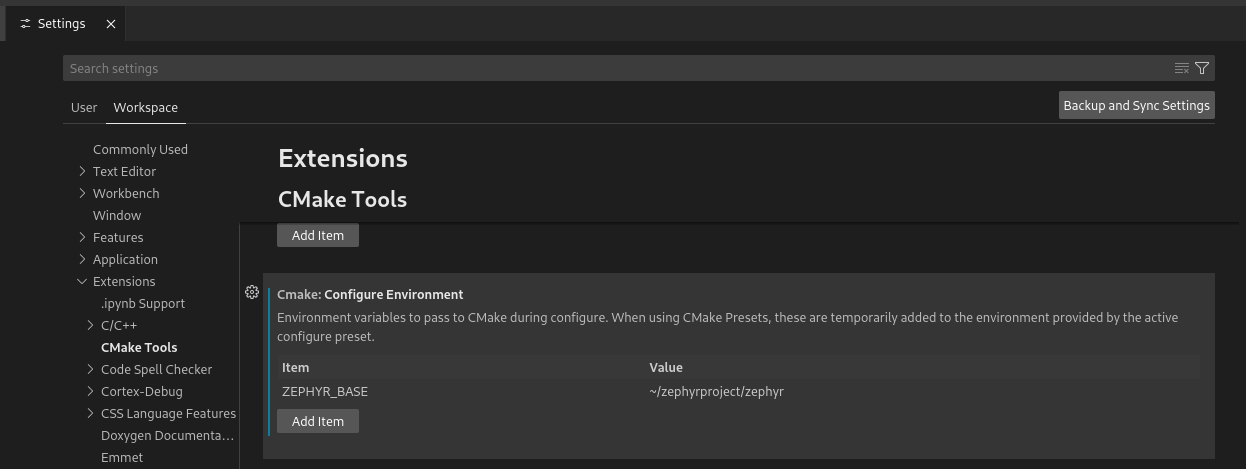
Then delete the build directory created by CMake and start a fresh CMake build. If the output shows version 3.7.1, then ZEPHYR_BASE was set correctly.
Background
In this second assignment, you are going to rewrite the top-level architecture of a synthesizer to be able to generate proper sound. However, before getting started with the code, you should know a little bit about sound synthesis.
Before the creation of synthesizers, all the music that you could hear had previously been recorded using instruments and was optionally stored in some medium such as vinyl records. After its invention, the synthesizer allowed producers to create sounds from scratch, no instrument was needed. As with the first computer, the first synthesizer was analog and extremely bulky. It was created by Robert Moog in 1965 and contains all the elements present in the one you are going to use. Composer Wendy Carlos popularized the synthesizer a couple of years later with her album Switched-on Bach and this video that showcase its use (this is arguably the most influential music production video).
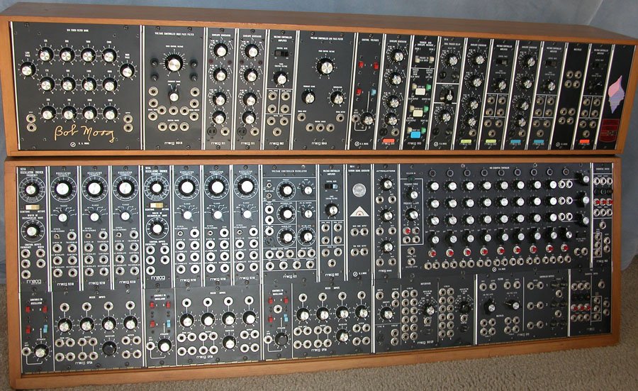 Figure 1: The Moog Synthesizer
In short, a music synthesizer is a device that can generate sound by electronic means. Furthermore, it can be used to control and modify the generated sound.
The synthesizer that you are using has the basic building block that can be found in any commercial synthesizer:
- 2 oscillators with the four classic waveform types (sine, square, triangle, and sawtooth)
- A low-pass filter
- Low-frequency oscillators
- Amplitude modulation envelopes (not yet implemented)
- Additional effects (not yet implemented)
If you want to read more about each building block, you can check this introductory guide.
Synthesizer Hardware
Synthesizer electronics
The synthesizer electronics consist of two main components (see Figure 2). The first is a development board with a microcontroller which is used to host the Zephyr OS and the synthesizer application code. This microcontroller is mounted onto the second main component, a printed circuit board (PCB) containing switches, encoders, and LEDs which you can use to interact with the synthesizer. We will refer to this PCB as the peripherals board.

Figure 4: the synthesizer board.
You can find the electrical schematic of the synthesizer here. This resource is provided in case you are interested in how it has been implemented, but you don't need it for the assignment. As you will have access to the physical board, you can also see where each of the components in this schematic are located on the board.
If you don't come from an electrical background, you can also find simple guides on how to read datasheets on the internet like this one. This example is a nice one to get started.
Synthesizer interface
You can print information from the synthesizer on your computer by using the micro USB serial port located at the bottom of the development board (CN5). Additionally, you can play notes by pressing keys on your keyboard and sending this information through the serial console. Refer to the lab setup if you don't know how to use a serial console. In Figure 3, you can see the keyboard mapping.

Figure 3: Computer keyboard layout. Credits to peachpit.com
If you are not familiar with music notes, don't worry - you are not required to play any meaningful melody or chord. For the whole assignment, you don't need any music proficiency :). However, if you are curious, you can see the corresponding musical notes in Figure 4:

Figure 4: Keyboard notes. Credits to smackmypitchup.com
To be able to continuously play notes with your synthesizer, we recommend using a terminal-like serial monitor like minicom, screen, or picocom that constantly sends your keyboard inputs to the development board. For an enjoyable user experience, the use of the Arduino or Microsoft Serial monitors is discouraged.
Synthesizer configuration
You saw the peripherals board that you will be using in Figure 2. The top half of the board is comprised of 6 LEDs (D1, D2, D4-D7), a switch (SW1) and three encoders (ROT1-3) that are mostly related to sound generation. The bottom half of the board, containing an LED (D3), three switches (SW2-4), and three encoders (ROT4-6), is dedicated to sound shaping. Below you will find a description of how the synthesizer is configured using these peripheral components. However, if you don't care, just toggle SW1 out of its neutral position and, if you press a valid key in your keyboard, you should hear sound produced. To get a basic view of the different building blocks of a synthesizer, we recommend reading this introductory article.
If you just want to produce a basic sound, switch up the top switch and when you press a valid key a sound should play. To get a basic view of the different building blocks of a synthesizer, we recommend reading this introductory article. Our synthesizer is divided into two parts. The top part controls the two oscillators, which are responsible for the sound generation as well as the master volume and the low-pass filter. The bottom part controls the modulators and the special effects. Below you can find information about each feature.
Top Half
This synthesizer has two oscillators which are selected by toggling the top switch out of its neutral position. D5 lights up to indicate that you are selecting oscillator 1, while D6 lights up to indicate that you are selecting oscillator 2. ROT1 controls the the waveshape of the oscillator; you can select between square, sine, triangle and sawtooth. You should see a message on the console each time you change the waveshape. ROT2 controls the amplitude/volume of the selected oscillator while ROT3 selects its frequency/pitch. The oscillators can be configured and used simultaneously. To use both oscillators, it suffices to select the first oscillator, raise its amplitude, and then select the second oscillator and raise its amplitude.
When the top switch is in its neutral position (in the middle position, when no LED is on), ROT2 controls the general volume of the composite sound (the combined sound produced by oscillator 1 and 2). Additionally, with the top switch in this state, you can also control a low pass filter (pending feature). ROT1 sets the cutoff frequency for the filter, while ROT3 adjusts the filter's resonance frequency. The table below summarizes all these configurations:
| Top switch | Encoder 1 | Encoder 2 | Encoder 3 |
|---|---|---|---|
| Up: Oscillator 1 | Waveform | Pitch | Volume |
| Down: Oscillator 2 | Waveform | Pitch | Volume |
| Neutral | LPF resonance (pending feature) | LPF cutoff frequency (pending feature) | Global volume |
Bottom Half
Now let's move to the lower half of the board. SW2 selects between different effects that can modify the sound outputted by the synthesizer. If it is switched up, you are selecting the low-frequency oscillators (LFOs) Modulators (LFOM). If it is switched down, you are selecting the Amplitude Modulators (AM). These are not yet implemented, but if you like the project, you can contribute to the project. When the switch is in its neutral position, we are considering adding special effects like phasers, delays or distortion. Again, you are free to implement new features and contribute to the project.
The parameters of the LFO modulation are set with 2 out of the 3 bottom encoders. ROT4 sets the amplitude of the LFOs, while ROT5 sets their frequency. For now, ROT6 is not used since it will only configure the amplitude modulators. The amplitude modulation parameters can be set with the 3 bottom encoders. We follow the classical ADSR (Attack, Decay, Sustain and Release) envelope. ROT4 sets the Attack and the Decay, ROT5 sets the Sustain and ROT6 sets the Release. Amplitude modulation is a pending feature.
SW2 | Encoder 4 | Encoder 5 | Encoder 6 |
|---|---|---|---|
| Up: LFOM | Amplitude | Pitch | None |
| Down: AM | Attack and Decay | Sustain | Release |
| Neutral: TBD | TBD | TBD | TBD |
The LFOs and AM modulate a particular configuration. This is controlled by SW3. Again, all you need to know is here in this introductory article. When SW3 is in its upper position, it modulates the selected effect on Encoder 2 and when SW3 is in its lower position, it modulates the selected effect on Encoder 3. The selected effects are determined by the position of the top switch. If this sound a little bit confusing just try playing around with the knobs, every time you change the position of a switch, you should see information printed with the configuration you selected.
| Top switch | SW3 | Modulation |
|---|---|---|
| Up: Osc 1 | Up | Osc 1 pitch |
| Up: Osc 1 | Down | Osc 1 volume |
| Down: Osc 2 | Up | Osc 2 pitch |
| Down: Osc 2 | Down | Osc 2 volume |
| Neutral | Up | LFP cutoff frequency (pending feature) |
| Neutral | Down | Master volume |
Status LEDs
There are additional LEDs in the upper-right corner of the peripherals board that can provide additional information about the state of the synthesizer. D5 indicates if the processor is currently running: its pulse width is equal to the processor's utilization. D7 indicates if it is currently overloaded. The rest of the LEDs don't have any function yet. We are open for suggestions!
NOTE: in the assignment, you will be asked to implement the toggling of
D7to indicate if the system has been driven into overload.
Project structure
Here is an overview of the project structure to help you get started with the assignment. More detailed information regarding the structure of Zephyr projects can be found here.
In the root folder, you will find three important files:
CMakeList.txtis part of every C project and tells the compiler how to compile your project.prj.confallows the user to configure Zephyr's features. Every board (in this case, the stm32f4_disco) already has an initial configuration. With this file, you can customize Zephyr on top of the initial configuration specific to your board. For instance, withCONFIG_CPP, we tell Zephyr that we want to be able to write C++ code in our application. You don't need to modify it, but you are free to do so. You can find a reference of the CONFIG options here.app.overlayallows the user to specify additional hardware peripherals. These peripherals are organized into a device tree, a Domain Specific Language (DSL) used by Linux to describe the hardware of an operating system. In a similar fashion toprj.conf, your board has an initial device tree, and you can extend it with this file. You can find more information about the device tree in Zephyr here.
In the src folder, you can find all the synthesizer application source code:
- The
audio, buffer, i2c, leds, peripherals, RotaryEncoder, Switch,andusbsource files contain drivers and utilities for using them. Except foraudio, you don't have to modify them, buy they contain functions that you might need to use. - The
filter, key, lfo, sineandsynthsource files specify the functionality of the synthesizer.synthis the main file where you can compute the output sound, andkeyis the data abstraction for musical notes generated by your laptop keyboard and processed by the synthesizer. Thefilterandlfofiles specify the configuration of the low-pass filter and low-frequency oscillators, respectively. In the beginning, you won't have to modify anything in these files, but you likely will in later stages. mainis the file you are going to be modifying the most. It contains the main thread that calls all the synthesizer libraries, and you should be able to complete nearly the entire assignment by only making modifications in this file. However, to organize your code, you may want to create additional files that are then included bymain. This is optional.
NOTE: Should you choose to split up
main, please document the new design in your report.
During the whole project, you are free to play with the synthesizer. However, bear in mind that, if the synthesizer goes into overload and misses deadlines with the audio amplifier, a very annoying sound will play.
Assignment Instructions
This assignment requires you to roll back to Zephyr 3.7.1 or earlier. Follow this guide to rollback your Zephyr installation before starting on the assignment, if you have not already done so!
Part I: First encounter with the synthesizer
Before making any changes to the system, it is first necessary to understand the structure of the system, the tasks it performs and other relevant parameters, that must be considered in the new design.
The synthesizer performs four main tasks:
- Task 1: check if the state of any peripheral (switch or rotary encoder) has been changed and update the appropriate synthesizer data structures.
- Task 2: check and process the input keys from the keyboard.
- Task 3: synthesize/generate the sound to be played.
- Task 4: send the generated sound to the audio amplifier.
Each of the tasks have been mapped to an LED. Refer to the source code, the development kit documentation and logic analyzer documentation for the correct pin mappings.
For this part, you don't have to modify the code, but you might need to read parts of the code to understand what each task does.
In the lectures, quizzes and exercises, you have been mostly working with fixed execution times. However, in real life, execution times are not always fixed and depend on Use Cases. This is also the case with the synthesizer you are going to redesign.
- [8 points] Question 1:
- For tasks 3 and 4, measure with the logic analyzer the average (AECT) and worst case execution time (WCET) when
SW_OSC1is in the up position and one note is playing.NOTE: In case of Task 4, make sure to measure the execution time right after start-up as the task's execution time increases with time due to some compiler issues.
- For tasks 1 and 2:
- First define Use Cases that will lead to the average and worst case execution time. Explain these Use Cases in your report.
- Recreate these use cases (by playing notes or triggering the switches or the rotary encoders) and measure the average and worst case execution times using the logic analyzer
- Translate the average and worst case execution time in % of Processor Utilization (PU) and record these values in your report.
- Task 3 is the less time-sensitive task. Therefore, in theory, it could execute when none of the other tasks are running. Reason how much PU you would assign to Task 3 inside the
superloop.
- For tasks 3 and 4, measure with the logic analyzer the average (AECT) and worst case execution time (WCET) when
Part II: Synthesizer tasks overhaul
As you might have noticed, executing all the tasks sequentially in a superloop is not a great idea, as each task has different latency requirements. Additionally, some tasks might overrun their expected utilization time and make other tasks miss their deadlines. This can partially be solved by limiting the processor utilization or by taking into account the worst-case execution time of each task, these decisions have a huge impact on the performance of the system. For this reason, you will assign Zephyr threads to the 4 tasks.
This does not necessarily mean that you have to use a separate thread for each task. You can use one thread for several tasks if you believe this to be the best design.
We recommend reading Zephyr's Scheduling and Threads documentation before designing your implementation.
However, before you start coding:
- [4 points] Question 2: Determine the upper and lower bounds of each task's period. Think about what values are reasonable in regard to for example: system responsivity, timing constraints and preventing overloading. In your report, state the period's lower and upper bound for each task, and choose the period that you want to use for your implementation. Justify your answers. You are free to change your answers based on your observations post implementation as long as you justify your answers
Tip: the synthesizer's rotary encoders have 96 slits per turn.
- [4 points] Question 3: Set a priority for each thread. Justify your answer. Furthermore, consider the role of the thread executing
main()and clearly define its functionality in your design. The section Thread priorities might be useful to read.
Now you can start coding!
-
[10 points] Question 4: Separate the superloop into threads
- Separate the
superloopinto the threads you defined in the previous questions. Check that you can play a note with the two oscillators on and that the pitch and volume encoders are working fine. You can modify your previous answers of part II based on the results that you get here. - Task 4 needs to be executed with precision, so make sure to use an appropriate method for timing. You can find all timing options available here
- For some tasks like sound synthesis (Task 3), the execution time scales linearly with the period, leaving the processor utilization almost unchanged. For others, it might be constant and thus the processor utilization greatly increases when you lower the period. Compare the average and worst-case execution time and processor utilization of Task 1 (the peripherals task) from Question 1 with the ones obtained now, after separating the
superloopinto threads.
- Separate the
-
[8 points] Question 5: Some resources are shared between threads. Identifying race conditions becomes very important when using multiple threads as they may lead to undesired behavior. For instance, shared data structures and peripherals such as buses are considered resources and thus can produce a race condition.
-
Review the source code and identify all race conditions and report these.
-
In your report, for each race condition:
- State whether it is tolerable or needs to be fixed and justify why
- State which threads are involved
- Explain when they may appear (which read/write operation may trigger them)
- Describe what impact it has on overall performance
- If you chose to fix it, explain your design and the consequences it has on the performance of the synth
If you want a refresher on what is a race condition, you can read this guide and/or this guide, as well as the Software Systems course lecture notes. You can find Zephyr's documentation for mutexes here. Of course, you are free to use the other synchronization methods.
Note: since the
printulufunctions are considered debug tools, you don't have to fix any of them. You don't have to fix race conditions associated with the audio buffer either. However, you have to describe them.
-
The last part that needs to be fixed is the audio buffer. Zephyr offers a kernel object to handle big chunks of memory of fixed size: memory slabs. Currently, the audio is stored in a single buffer that is shared between the sound generation primitive and the data transfer to the audio amplifier (through DMA).
This is a typical example of a race condition, where the synthesizer is writing to the buffer at one speed and the audio buffer is reading from the buffer at another speed. In these cases, a common solution is to use one buffer to write the data and another one to read/transfer the data. This is known as double buffering.
- [8 points] Question 6: Implement double buffering for the audio buffer and explain your design.
Ensure that:
- The DMA never reads the same buffer as the sound function
- Buffers are freed and allocated correctly
- Only memory that is necessary is allocated
- The total allocated memory must never exceed the size of the Zephyr slab
We recommend reading up on how the
k_mem_slab_alloc()andi2s_write()function calls work before designing your implementation
If the double buffering has been implemented correctly, the resulting sound (when playing a single note) should be clear, without any clipping or beep.
Part III: Overload
If you play many notes at the same time and/or you apply too many sound effects, you will notice that the microcontroller's processor cannot compute the sound in time. Depending on how you have implemented Part II, you will hear an annoying sound when that happens. After implementing Question 7, no race condition should occur under normal operation. However, if the system is overloaded, you will run into a race condition.
- [8 points] Question 7: Implement overload detection, and handle overloading. Ensure you design meets the following requirements:
- The sound-synthesis task must identify when it drives the processor into overload and just before its deadline, must stop computing the sound of the current buffer, called frame and start computing the following one.
- For the next frame, LED
D7(red LED) must light up to indicate the user that they are driving the synthesizer into overload. - Ensure that the buffer is properly reset before sending the frame to the audio amplifier as it may not be possible to fill the buffer for a given frame
Properly reset implies the part of the buffer that is not filled must be set to 0. Do not use any other approach
Part IV: Interrupts
IMPORTANT: If you arrive to this part of the assignment, provide at the start of your report the hash address of your implementation with and without part IV.
Currently, to know if a peripheral has been updated, the processor periodically polls every peripheral and compares its current value with the previous one stored in the synthesizer's data structures. If the two values are different, then the state of the peripheral has changed.
Although this is simple to implement, there is a potential issue associated with this approach. If two consecutive state changes occur between two polls, one of them will be lost and, in the case of the encoders, an invalid state transition will be registered.
Here, you are asked to use interrupts instead of polling to check the peripherals. Bear in mind that interrupts have extremely high priority, so their execution time should be extremely short. You should not execute all the peripheral update code in the Interrupt Service Routine (ISR). You should simply capture the new peripheral's state and offload the work to a workqueue or another thread.
Here are some documents that you might find useful, when attempting Part IV:
- [8 points] Question 8: Move the code for updating the state of the 4 switches (8 pins) from the peripheral thread into separate interrupt handlers. You can find a very nice guide (based on an older version of Zephyr) here. Explain your design.
For each switch action, only one callback should be raised. Thus, you also need to implement software debouncing for the full points in this question. Document how debouncing been implemented in your report.
NOTE: The suggested guide makes use of an older definition of the
gpio_callback_handler_tstruct. The latest definition can be found here. Ensure that your design uses the new definition and not the old one, found in some the snippets in the guide (which no longer compiles).Tip: using anonymous functions can considerably reduce your code size and make it more readable. C++ implemented them in their 2011 version, which is the one Zephyr supports. You can find a guide here.
- [Bonus: 8 points] Question 9: Do the same but with the port expander that controls all the rotary encoders. Again, explain your design in the report.