4 FPGA Board
4.1 Setup
If you have done the previous steps succesfully, you are now ready to work with the FPGA board. Please take the following important note into account:
Each group receives a working and tested box containing the following items:
- FPGA board
- Power cable
- USB Cable
- Ethernet cable
- Micro SD card (inserted in the board)
It is possible to borrow the box and work with them outside of the lab sessions. However, all group memebers are responsible for returning the box back by the final report submission date. Failing to do so, would result in failure of the course for all members of the group.
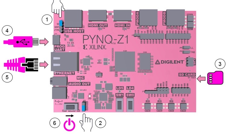
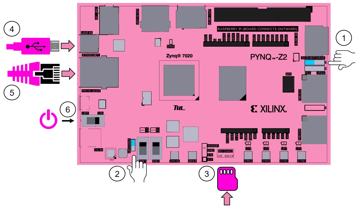
This project uses the PYNQ-Z1 or PYNQ-Z2 Board from Digilent. It has the ZYNC-7000 SoC device from AMD (formerly Xilinx) with a hardened ARM Cortex-A9 core directly connected to the Programmable Logic (PL). The communication with the board will be done via ethernet cable, which will be used to run Jupyter Notebooks in the processing system (ARM core). To be able to do this, the board needs to be set up as shown in Figure 15. For more information, see the board Z1 or Z2 manuals.
 |
|---|
 |
| :--: |
| Figure 15. PYNZ-Z1 and PYNZ-Z2 boards |
Follow the steps below:
- Set the JP4 / Boot jumper to the SD position by placing the jumper over the top two pins of JP4. This sets the board to boot from the Micro-SD card.
- To power the PYNQ from the micro USB cable, set the JP5 / Power jumper to the USB position. You can also power the board from an external 12V power regulator by setting the jumper to REG.
- Insert the Micro SD card loaded with the PYNQ image into the Micro SD card slot underneath the board.
- Connect the USB cable to your PC/Laptop, and to the PROG - UART / J14 MicroUSB port on the board.
- Connect the board to Ethernet by following the instructions below.
- Turn on the PYNQ and check the boot sequence (explained below).
Boot sequence:
-
Slide the power switch to the ON position to turn on the board. The Red LD13 LED will come on immediately to confirm that the board has power. After a few seconds, the Yellow/Green LD12 / Done LED will light up (green) to show that the ZYNC device is operational.
-
After a minute you should see two Blue LD4 & LD5 LEDs and four Yellow/Green LD0-LD3 LEDs flash simultaneously. The Blue LD4-LD5 LEDs will then turn on and for some seconds and then turn off while the Yellow/Green LD0-LD3 LEDs remain on. The system is now booted and ready for use.
-
Connect the FPGA board to a computer:
You need a computer with a free Ethernet port [^1]1.
You also need to have the permissions to configure your network interface.
With a direct connection, you are able to use PYNQ.
Follow the steps below to connect directly to a computer using static IP2 address:
- Assign a static IP address (how to).
- Connect the board to your computer’s Ethernet port.
- Open a web browser and browse to
http://192.168.2.99. - The credentials to login on the web page are xilinx/xilinx.
4.2 Running on FPGA
Once logged in, the main screen of the Jupyter notebook is similar to Figure 16. If you are not familiar with Jupyter notebook, you may want to check this tutorial.
 |
|---|
| Figure 16. Jupyter notebook web page |
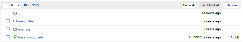
The content of the folder riscy is shown in Figure 17.
 |
|---|
| Figure 17. Folder content |
Inside mem_files you see data.coe and code.coe, which are the memory initialization files for the BRAMs connected to the RISCY core.
The overlays directory contains the following:
base_riscy.bit: Generated bitstream from the main riscy project, can be found inpdp-project/hardware/vivado/riscy/riscy.runs/impl_1/riscv_wrapper.bit.base_riscy.tcl: Generated at the same time as the bitstream, you can find it inpdp-project/hardware/vivado/riscy/riscy.runs/impl_1/riscv_wrapper.tcl.base_riscy.hwh: Hardware handoff file, autogenerated from the riscy project inpdp-project/hardware/vivado/riscy/riscy.gen/sources_1/bd/riscv/hw_handoff/riscv.hwh.
These 3 files will have different names when you generate them using Vivado. Then you should rename them to the same to be able to use them in the Jupyter Notebook and the name should match that of the bitstream when importing it with the Overlay command inside the Jupyter notebook.
You can find a copy of this base directory in pdp-project/hardware/sw/fpga/riscy.
With all the files available and accessible via the browser in the FPGA, you can now proceed to run the base_riscy.ipynb notebook.
This notebook contains the code and explanations to perform the following actions:
- Initialize the notebook, load the overlay (PL image/bitstream) and some helper functions to initialize the BRAMs.
- Program the PL with the bitstream.
- Control the RISCY core by performing AXI writes/reads to the riscv_control module.
- Programming the instruction and data memories.
- Read the instruction and data memories.
- Start/stop the fetching from the core.
- Check the results written by the core to memories or the duration of the test registered by the mem_snoop module.