Simulation & Synthesis
Simulation
Simulation is an important step when working on any FPGA project. It lets you test your code with custom inputs and access all the variables within your code. Additionally, for bigger projects, simulation has a much faster turn-around time rather and synthesizing your design and running it on the FPGA.
To simulate your project:
- Create a new testbench file
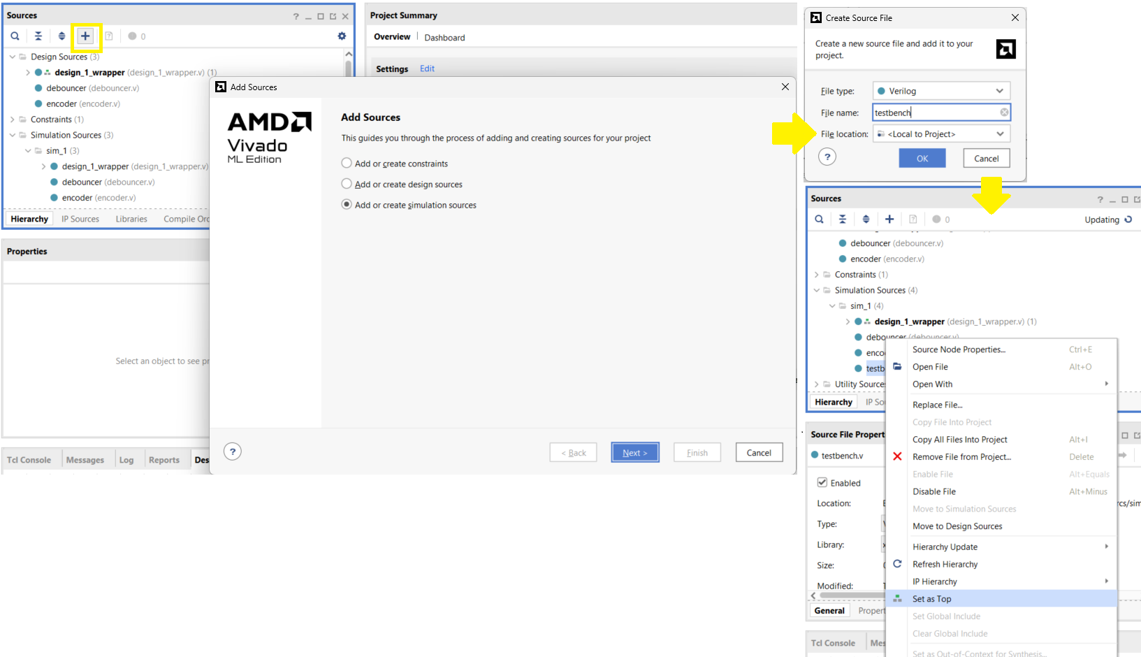
- With the project Open, select
Add Sourcesor pressAlt + A; selectAdd or create simulation sources - Select
Create File, name the filetestbench, thenFinish - Expand
Simulation Sourcesin theSourceswindow. - Right-click on your testbench file and select
Set as Top. Your testbench file name should be written in bold
- With the project Open, select
-
Write your test-bench
- Create an Instance of the module you want to test.
- Add code to modify the inputs to check various cases
- If the module under test has synchronous logic, simulate a clock signal in your testbench
// General testbench example `timescale 1ns / 1ps module testbench; reg clk; // Inputs as reg and outputs as wire reg reset; reg [3:0] input_signal; wire [3:0] output_signal; your_module uut ( // Instantiate the unit under test .clk(clk), .reset(reset), .input_signal(input_signal), .output_signal(output_signal) ); initial begin // Clock generation block clk = 0; forever #5 clk = ~clk; // Invert clock signal every 5 time units end initial begin // Stimulus block reset = 1; // Initialize inputs input_signal = 0; #10; // Wait to un-toggle reset reset = 0; #10 input_signal = 4'b0001; // Test inputs #10 input_signal = 4'b0010; #10 input_signal = 4'b0100; #10 input_signal = 4'b1000; #50; // Wait and finish $finish; end endmodule -
Simulating your design
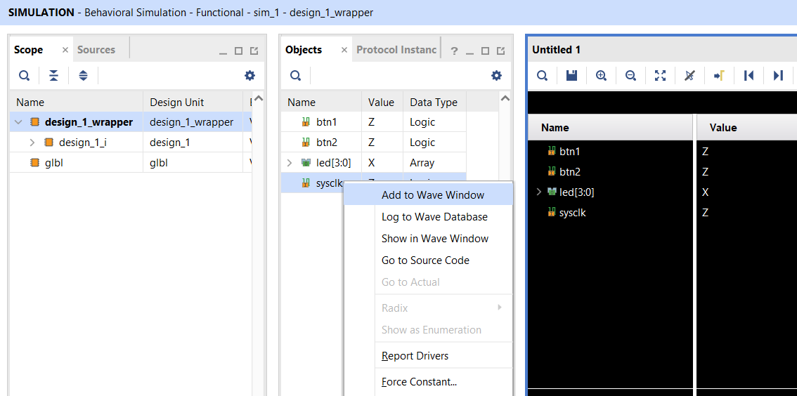
- Launch the simulation by selecting,
Flow Navigator -> SIMULATION -> Run Simulation -> Run Behavioral Simulation. - When the simulation you defined in your testbench is complete, open the waveform viewer to view your signals.
- You can add more signals to the
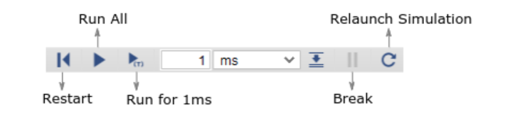
Wave Window. You can find more by expanding theSourceson the left side of the window. After you add a new signal you must reload the simulation to see the new signal changing. - Use the controls on the top taskbar to start/stop the simulation
- Do not forget to resize your simulation window, so you can see the signals for the entire duration of the simulation
- Launch the simulation by selecting,
Running Project on FPGA
Once the project is working as expected in the simulation, you need to generate the bitstream to upload to the FPGA.
Run Program on the FPGA:
-
Generate Bitstream
- Select
Flow Navigator -> PROGRAM AND DEBUG -> Generate Bitstream - This will generate the bitstream for your project. This step may take up to 5 minutes to complete. So prefer the simulation to verify the correctness of your code.
- Select
-
Connecting to the FPGA
- Connect the FPGA to the Laptop using the USB Cable and turn ON the FPGA switch if it is OFF
- In Vivado select
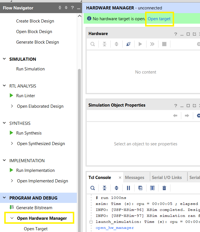
Flow Navigator -> PROGRAM AND DEBUG -> Open Hardware Manager - Select
Open targetat the top of the window, then selectAuto Connect
-
Program the FPGA
- Right-click on the FPGA, select
Program Device - Select the bitstream that was generated in the previous step. It can be found in
<project_name>\<project_name>.runs\impl_1. - Program the FPGA
- Right-click on the FPGA, select
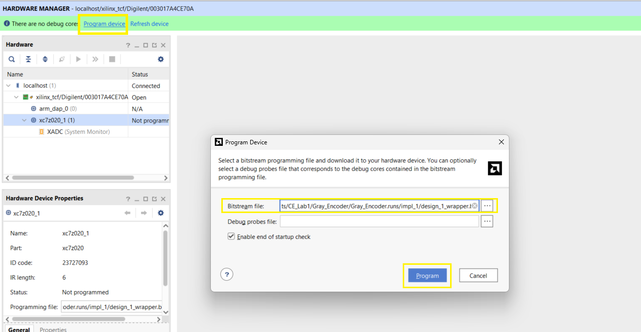
Your FPGA is now programmed and running the Verilog code that you wrote!