The MLite CPU
The MLite CPU is a small synthesizable 32-bit RISC microprocessor that executes all MIPS I [11] user mode instructions except unaligned load and store operations. In the VHDL code the CPU top module, which includes the cpu (mlite_cpu unit), and the AXI4 read and write controllers, is represented by the cpu unit.
Program Counter
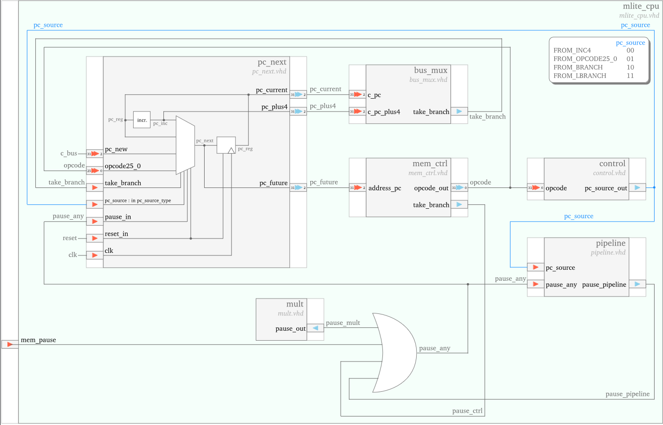
The pc_next unit generates the address of the next instruction on its pc_future output port.
The value of pc_future can either:
- be the incremented value of the previous program counter (stored locally in
pc_reg) - come directly from the mem_ctrl unit (on the
opcode25_0input port), in case of an unconditional branch - be computed by the alu unit and received on the
pc_newinput port, in case of a conditional branch
The selection is performed by the pc_source signal, generated by the control unit.
In case of a conditional branch, the take_branch signal is also utilized in the selection:
pc_future takes the pc_new value when take_branch is 1,
and the previously incremented program counter values when take_branch is 0.
Memory Interface
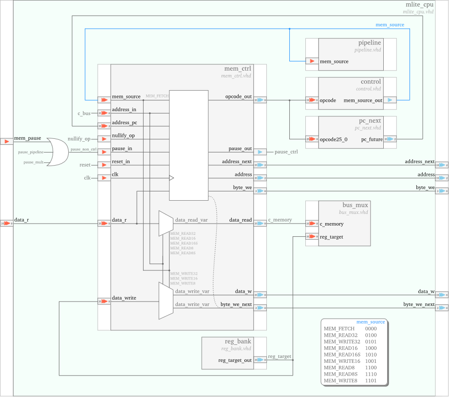
The mem_ctrl unit is managing the cpu to memory communication:
it sends addresses to memory, and both receives data from and sends data to memory.
The unit is controlled through the mem_source signal,
issued by the control unit,
to perform one of the following tasks:
- Instructions fetch:
– it sends the appropriate instruction address, received from the
pc_nexton theaddress_pcport, to the memory – it receives the instruction opcode on its data_r port; – it delivers the instruction opcode to the control unit on its opcode_out port. - Data memory read (for load operations): – it sends to the memory the address of the data to be loaded; – it receives the data from memory and it passes it to the bus_mux unit;
- Data memory write (for store operations): – it sends to the memory the data and the where to be written address.
Decode and Control
The control unit performs instruction decode, based on which it generates the control signals for all the other units.
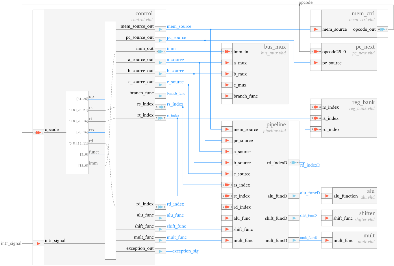
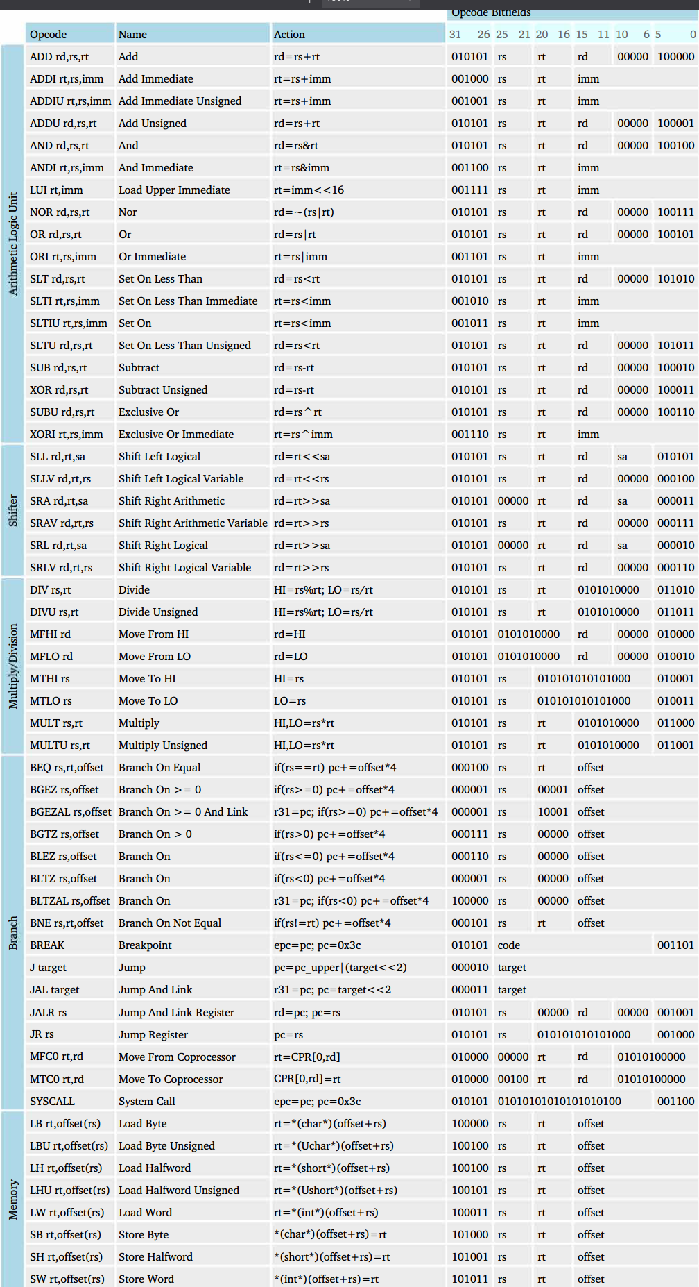
The actual logic behind what control signals are sent, depends on the instruction set:
Bus
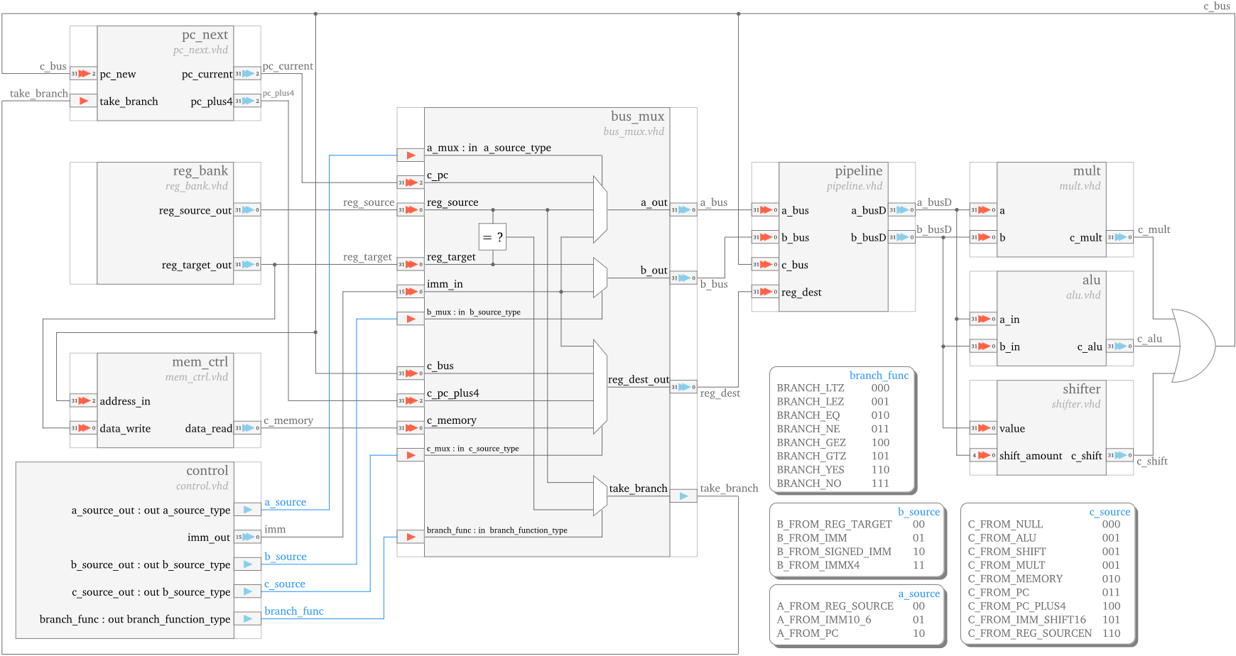
The main task of the bus_mux unit is to perform the functional units input signals multiplexing.
In addition, the bus_mux unit also performs the comparison required by the conditional branch instructions,
and it generates the branch taken/not taken signal on its take_branch port.
Register File
The MLite CPU is based on the MIPS I instruction set, hence it embeds 32 32-bit general purpose registers. From the user (compiler) perspective, each register has a specific function, detailed below. You can use the table to find the mapping between the software register name (the one present in the benchmark assembly listing) and the hardware address of the register in the register bank.
The only functions that also need support from the hardware implementation are the following:
- The value of register R0 is always zero
- R31 is used as the link register to return from a subroutine
In addition to the general purpose registers there are 4 special registers, also detailed below.
- HI and LO registers contain the 32-bit MSB and LSB part, respectively, of a 64-bit multiplication/division result.
- The Program Counter (PC) specifies the address of the next instruction in the program.
- The Exception Program Counter (EPC) register remembers the program counter when there is an interrupt or exception.
- There is no status register. Instead, the results of a comparison set a register value, and the branch then tests this register value.
| Register | Name | Function |
|---|---|---|
| R0 | zero | Always contains 0 |
| R1 | at | Assembler temporary |
| R2-R3 | v0-v1 | Function return value |
| R4-R7 | a0-a3 | Function parameters |
| R8-R15 | t0-t7 | Function temporary values |
| R16-R23 | s0-s7 | Saved registers across function calls |
| R24-R25 | t8-t9 | Function temporary values |
| R26-R27 | k0-k1 | Reserved for interrupt handler |
| R28 | gp | Global pointer |
| R29 | sp | Stack Pointer |
| R30 | s8 | Saved register across function calls |
| R31 | ra | Return address from function call |
| HI-LO | hi-lo | Multiplication/division results |
| PC | Program Counter | Points at 8 bytes past current instruction |
| EPC | Exception | PC Exception program counter return address |
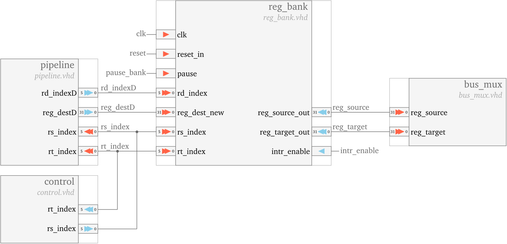
The interconnection of the reg_bank unit with the rest of the units is pictured below. It is implemented using two dual port memories.
Functional Units
The MLite CPU has three functional units:
- an ALU
- a Multiplier/Divider
- a Shifter
The ALU (alu.vhd) executes arithmetic and logic operations, with a delay of 1 clock cycle.
The adder in the ALU is described in behavioral VHDL as a ripple-carry adder.
The serial Multiplier/Divider (mult.vhd) takes 32 cycles to compute the 64-bit multiplier result,
or the 32-bit quotient and the he 32-bit remainder.
The pipeline is stalled during the mul/div operation by asserting the pause_out signal.
The Shifter (shifter.vhd) performs left and right bit-shifting in 1 clock cycle.
Pipeline
The pipeline unit contains the pipeline registers (flip-flops) that delay the inputs of the functional units and of the register file write port. Other separation registers between pipeline stages are placed in their corresponding modules.