Lecture 5
Introduction to Model-Based Development
What are some examples of complex systems?
- Drone swarm
- Philip's X-ray system (looks like this student has already looked at the assignment)
- ASML machine to create computer chips
- Missile system
What makes a problem complex?
- Many interacting components
- Large code-base which is difficult to test
- Code is reused for many generations of products
- Multiple teams cooperating (with different domain knowledge)
- Performance requirements
- Dependability requirements (might have to stay online for many years)
How to deal with complexity?
- Divide and Conquer, modularity
- Top-down or bottom-up approaches to design
- Small and targeted test-suites
In this course we describe these four approaches:
- Abstraction: Identify high-level concepts that hide low-level details
- Boundedness: Impose acceptable restrictions on the considered problem space
- Composition: Divide one problem into multiple independent smaller problems
- Duplication: Use multiple overlapping approaches for the same problem (redundancy)
What is model based development?
- Models capture "the essence" of the system to help understand the behavior of the system
- Communicating ideas
- Early validation
- Automated testing
More acronyms to keep in mind:
- KISS = Keep it simple, stupid
- DRY = Don't repeat yourself
Unified Modeling Language (UML)
Three categories of UML diagrams:
- Structure
- Behavior
- Interaction (subcategory of Behavior)
UML is a collection of standardized graphical notations.
Why bother with UML?
- Clarity: bring clarity to complex design
- Communication: a universal language for diverse teams
- Documentation: a valuable way for future reference
Use case diagrams
- Collection of actors, use cases, and their associations.
- Describes a very high-level overview of the system from an outsider's perspective.

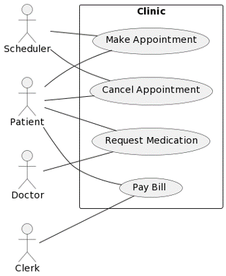
What do you see in this diagram?
- The clinic has all the features that you want. The people on the left are interacting with the clinic. The patient has access to most of the system.
- Maybe there should be directions from the actors to the use cases? (No. See below.)
- There are actors on the left, use cases inside the system, and associations that show which use cases are associated with which actors.
A use case diagram shows us who are the users of the system and how they interact with it.
There are four different types of elements in a use case diagram:
- Actor: represents a role played by a user or any other system that interacts with the system being modeled.
- Focus: who will use the system?
- Represented by stick figures
- Actors must be external entities
- Use case: summary of scenarios
- Represented by horizontal ovals
- System boundary: separates actors and use cases
- Defines the scope of the system
- Associations: illustrates the relationship between an actors and use cases
- Represented by solid line between an actor and a use case (no arrow!)
The students were given a task to create a use case diagram based on this system description:
Imagine a Library System that has two main types of users: Library Members and Librarians. Library Members can use the system to borrow books to take home and return books when they have finished reading. They can also search their book of interest. On the other side, librarians are responsible for updating the catalogue and managing memberships. Both library members and librarians can search books.
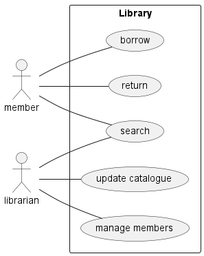
Here is the diagram Brendan created on the board during class (recreated in PlantUML):

PlantUML code:
' Brendan's diagram

@startuml library
left to right direction

actor member
actor librarian

rectangle Library {
    usecase borrow
    usecase return
    usecase search
    usecase "update catalogue" as update
    usecase "manage members" as manage
}

member -- borrow
member -- return
member -- search

librarian -- search
librarian -- update
librarian -- manage

@enduml
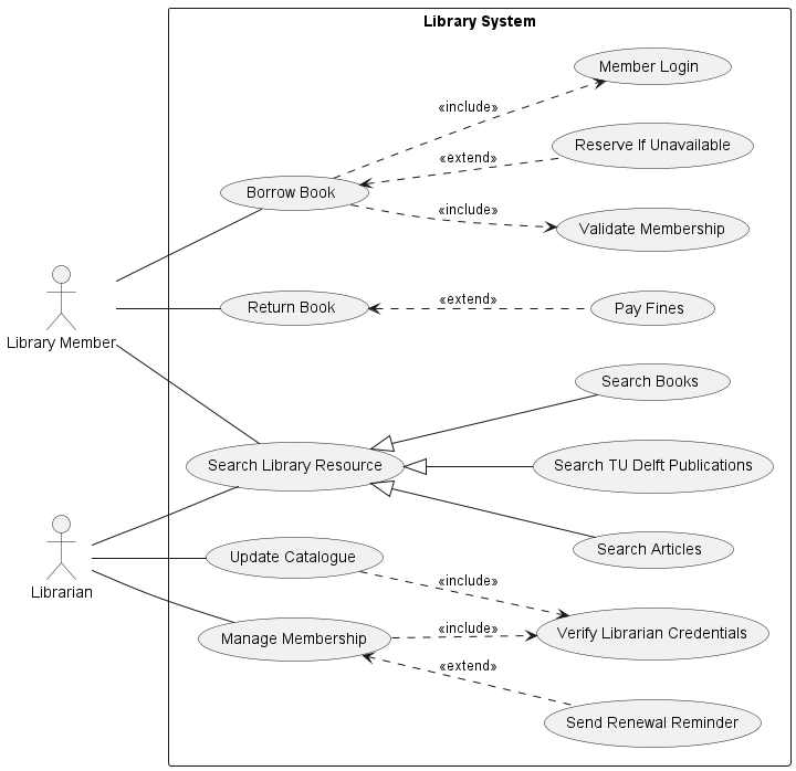
Later we looked at a more detailed model of the same system.

What has changed?
- More information has been specified
- Increased complexity
- Different types of relationships (See below)
Generalization:
- One use case is a more general version of another use case
- Empty arrow head
Include:
- One use case is a substantial part of another use case
- Dashed arrow
- Stereotype
<<include>>
Extend:
- Optional / conditional component of a use case
- Dashed arrow
- Stereotype
<<extend>>
When would we use a use case diagram?
- During the design of complex systems to keep track of interactions between systems (Isn't this true for all modeling methods?)
- Communication with non-technical members of the team, communication with the client
- Typically used in the early phase of the design