Component Diagrams
This tutorial covers component diagrams. First, we cover how to use PlantUML to create these diagrams, followed by two small exercises to practice drawing these diagrams.
More information on using PlantUML can be found on the official PlantUML website.
More information on component diagrams in UML can be found in section 11.6 of the UML specification.
Component and Interface
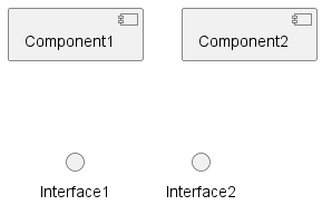
You can create a component by using the keyword component followed by the name of the component,
or by using brackets: [component_name].
To create an interface you can use the keyword interface followed by the name
or by using parenthesis: () interface_name.
@startuml components-and-interfaces

' Create two components
[Component1] as c1
component Component2 as c2

' Create two interfaces
() Interface1 as i1
interface Interface2 as i2

@enduml

Connecting Interfaces
To create associations between components and interfaces
write component_name -- interface_name
and component_name --( interface_name for the provider
and receiver of an interface respectively.
@startuml connecting-interfaces

[Provider] -- Something
[Receiver] --( Something

@enduml
Packages and Databases
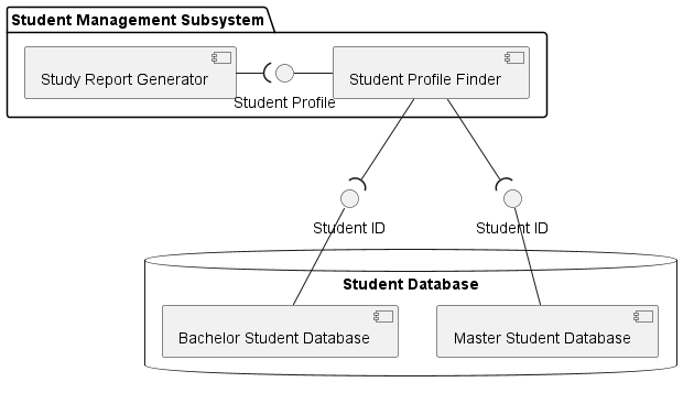
You can also group several components into
a group or package by using the package keyword.
You can also group components into a database using
the database keyword.
@startuml packages-and-databases

package "Student Management Subsystem" {
    component "Student Profile Finder" as SPF
    component "Study Report Generator" as SRG
    interface "Student Profile" as SP

    SRG -right-( SP
    SPF -left- SP
}


database "Student Database" {
    component "Bachelor Student Database" as BSD
    component "Master Student Database" as MSD
}

' We create two interfaces because
interface "Student ID" as SID1
interface "Student ID" as SID2

MSD -up- SID1
BSD -up- SID2
SPF --( SID1
SPF --( SID2

@enduml

Exercises
1. ATM Transaction
Draw a Component Diagram for an ATM transaction:
A user is interacting with an ATM with his credit card. Specifically, he can interact with the GUI of the ATM which provides the following options:
- Balance Check
- Money Withdraw
- Deposit
The user starts the interaction by inserting the credit card into the card reader of the ATM. After authentication, he can choose one of the three options provided. Note that the ATM is connected to the Bank's database server where the user's account information is stored. When the transaction is complete, the ATM will save the transaction in a separate database, update the user's account information, and print the receipt if required.
(Hint: a dispenser is needed for 'Money Withdraw').
2. Online Shopping Diagram
Draw a Component Diagram for an online shopping scenario:
A customer has an account for her favorite online shop. When shopping online, the customer can add a desirable product to the shopping basket. When the customer is placing an order, the system will leverage an online payment service that is provided by a banking system. To complete the order, the shopping system will collect delivery details from the customer and arrange the delivery of the ordered products.