Lecture 7
Finite State Machines
Background and Motivation
What is an FSM?
- Mathematical model of computation.
- Diagram describing states that a system can be in and the transitions between these states.
- Model of computation with a finite number of states.
What parts (or type of logic) do you need to realize an FSM?
- A single start state
- An optional final state
- Transitions between states
- The other states
- Inputs/outputs
- Sequential logic to remember the state
- Combinatorial logic for the state transitions
What FSMs do we know?
- Moore: output depends only on the current state (outputs on states)
- Mealy: output depends on input and the current state (outputs on transitions)
What is a possible problem with simple FSM representations?
- Explosion of the number of states and transitions
FSMs are a practical way to describe behavior
- User workflow: In which environment will the system be used?
- System behavior: What is the logic that the system should implement?
- Communication protocols on interfaces: How should concurrent components interact with each other?
Exercises
We looked at and discussed several finite state machines. Students were asked to explain how each state machine worked.
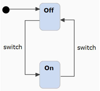
What would the elements in this FSM mean?
- Two states (On, Off)
- A start state (Off, pointed to by black circle called entry point)
- No terminal state
- Two transitions (Off -> On: switch, On -> Off: switch)
- This diagram describes the behavior of a light switch (based on the picture on the right) which begins in the Off state and can alternate between Off and On when switched.
- Does the light switch on the transitions or at the states? Is this a Mealy or Moore machine? The diagram does not say.
See the slides for an explanation of states, transitions, and events.
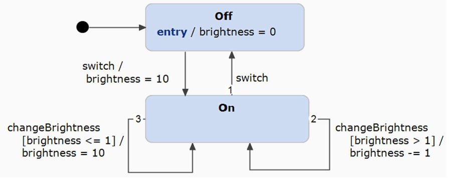
What would the elements in this FSM mean?
- Same states as previously (Off and On, with Off as start state)
- On
entryto Off, setsbrightnessto 0. - On switch from Off to On, set
brightnessto 10. - When in On and the
changeBrightnessevent is received- if
brightness<= 1: set to 10 - is > 1: decrease by 1
- if
- On switch from On to Off, run entry of Off again
Q: Is there an infinite loop? Maybe transition 3 would set the brightness to 10 and then transition 2 would loop, decreasing the brightness by 1, until transition 3 is valid again and repeat.
A: No, the transitions are only triggered on the changeBrightness event.
Q: Can you have transitions which do not cover the whole space of possibilities?
(Such as changing the condition on transition 3 to brightness > 2.)
A: Yes, it is possible, but the diagram no longer models what you want.
Explanation of transition 3
- Triggering event
changeBrightness - Condition
[brightness <= 1] - Action
brightness = 10
See the slides for an explanation of variables, guards, and effects.

What would the elements in this FSM mean?
- New in this FSM: transition using
after. - On
entryto Off:brightness= 0 motionDetectedevent in Off triggers transition from Off to On- on
entryto On:brightness= 1 motionDetectedeven in On triggers transition from On to On (loop)- after 30s in On there is a transition to Off
The result is that the FSM will stay in On after motion is detected until there is no motion for 30 seconds. Then it will transition back to Off.
Modeling skills
Ship lock
- two gates (bottom and top)
- two valves (paddle, culvert)
Why is this system interesting to model?
- We want to guarantee safety
- Catastrophic results if both gates are open at the same time
Task: Create diagram that models this system Assume:
- For the valves we rely on time to fill/empty the transition zone.
- For the gates we rely on sensors that confirm certain positions. User interaction:
- Start the next swap
- Possible extension: interrupt a swap?
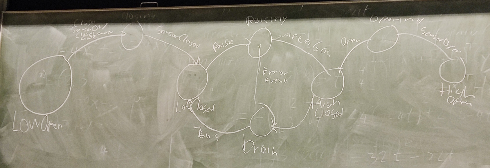
Here is how Hidde modelled the system on the board:
Here is a recreation in UML:
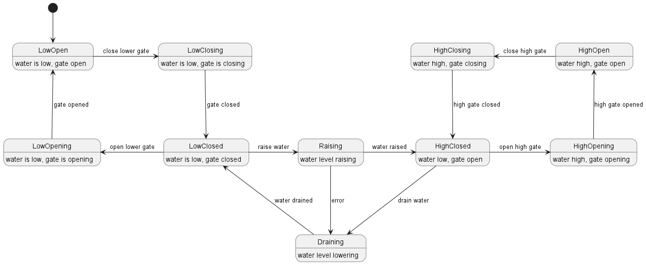
During class we discussed how the model could be simplified by removing certain states. We also appreciated the thought put into handling errors during the Raising state.
Advanced FSM Features
Composite States

What would the elements in this FSM mean?
- Two composite states (MotionSensing and Manual)
- Sub-states inside these large states
- This is a combination of two previous state machines
- Toggle between the two composite states on
ToggleModeevent
Q: When switching between the composite states, do we go from On to On in the other state, or do we always start in Off?
A: We always start in Off, because that is the starting state in both composite states.
Multiple Entries
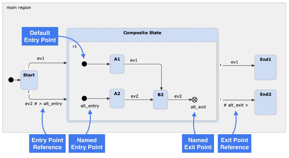
- Multiple entry nodes are possible (with unique names).
- Multiple exits are also possible.
- History nodes allow you to remember which state was active last when we left the composite state.
Q: What happens if we are in B2 receive both events ev1 and ev2 at the same time?
A: itemis CREATE only allows one event at a time, so we cannot simulate it.
Q: Is it compulsory to have a loop in the FSM?
A: Nothing is compulsory, we can have terminal states. It depends on what you are trying to model.
Orthogonal states
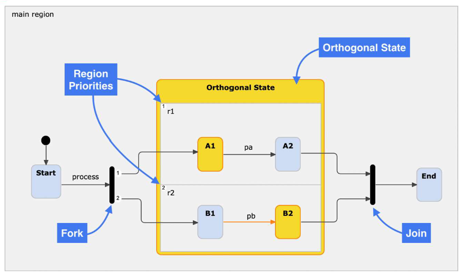
- Orthogonal states allow you to have two or more parallel state machines in one composite state.
- Fork nodes are used to enter into multiple states (otherwise we would only enter the first FSM)
- Join nodes are used to synchronize execution: they wait until all orthogonal state machines have reached the required states.
- Orthogonal regions can communicate via internal events.
How can we exploit FSM models?
- Communication
- With customers: model specification / requirements
- With developers: model of the implementation
- Generation of code
- Validation and verification of model
- Validation and verification of behavior
#/media/File:Canal_lock.svg)