Use Case Diagrams
This tutorial covers use case diagrams. First, we cover how to use PlantUML to create these diagrams, followed by two small exercises to practice drawing these diagrams.
More information on using PlantUML can be found on the official PlantUML website.
More information on use case diagrams in UML can be found in section 18.1 of the UML specification.
Actors and Use Cases
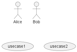
You can create an actor by using the keyword actor followed by the name of the actor
or by using the colon: :actor_name:
To create a use case you can simply use the keyword usecase followed by the name of the use case
or by using the parenthesis: (use case_name)
@startuml "actors and use cases"

' Create two actors Alice and Bob with aliases A and B.
:Alice: as A
actor :Bob: as B

' Create two use cases with aliases use1 and use2.
(usecase1) as use1
usecase usecase2 as use2

@enduml
Associations
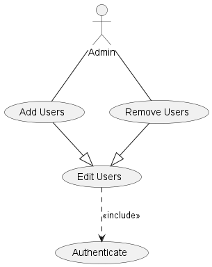
To create simple associations between use cases and actors, write actor_name -- use_case or use_case -- actor_name.
For generalizations use -|>, and for include or extend relationships use .> with the desired stereotype after a colon :.
The more dashes or dots you add to the arrow, the longer the line. Compare
.>and...>.
@startuml associations

' Create an actor and several use cases
actor Admin as admin
usecase "Add Users" as add
usecase "Remove Users" as remove
usecase "Edit Users" as edit
(Authenticate) as authenticate

' simple association
admin -- add
admin -- remove

' generalization
add --|> edit
remove --|> edit

' include
edit ..> authenticate: <<include>>

@enduml
System Boundary
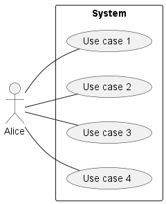
The system boundary separated use cases from the actors.
You can use the keyword rectangle to form a system boundary.
@startuml system-boundary
left to right direction

:Alice: as alice

' Create a system boundary
rectangle "System" {
    ' Define use cases within the boundary
    (Use case 1) as uc1
    (Use case 2) as uc2
    usecase "Use case 3" as uc3
    usecase "Use case 4" as uc4
}

' Connect Alice to the use cases
alice -- uc1
alice -- uc2
alice -- uc3
alice -- uc4

@enduml
Simple Checkout Example
@startuml checkout
left to right direction

' Create two actors
actor Customer
actor Clerk

rectangle Checkout {
    ' We can make the associations inside the system
    Customer -- (Checkout)
    (Checkout) .> (Payment) : <<include>>
    (Help) .> (Checkout) : <<extend>>
    (Checkout) -- Clerk
}
@enduml
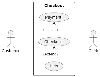
Note that the command
left to right directionwas used in the code above. Try copying the code to your IDE and remove that line. Do you see any difference?The output is displayed in the
top to bottom directionby default which can be difficult to read. Always try to make your diagrams more readable by trying different styles.
Scale Checker Example
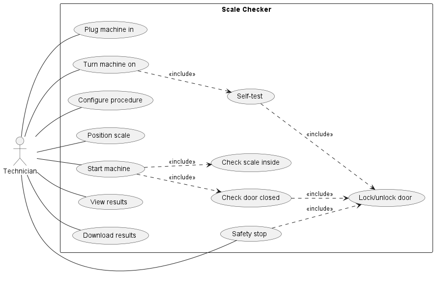
Below is a real-world use case diagram showing the use cases for a machine that checks scales inside a hospital. This diagram was created to provide an overview of what kinds of interactions exist between a technician and the machine before developing it further.
@startuml scale-checker
left to right direction

actor Technician

rectangle "Scale Checker" {
    usecase "Plug machine in" as plug_in
    usecase "Turn machine on" as turn_on
    usecase "Self-test" as self_test
    usecase "Lock/unlock door" as lock
    usecase "Configure procedure" as configure
    usecase "Position scale" as position_scale
    usecase "Start machine" as start
    usecase "Check door closed" as check_door
    usecase "Check scale inside" as check_scale
    usecase "Safety stop" as stop
    usecase "View results" as view
    usecase "Download results" as download
}

Technician -- plug_in
Technician -- turn_on
turn_on ..> self_test: <<include>>
self_test ..> lock: <<include>>
Technician -- configure
Technician -- position_scale
Technician -- start
start ..> check_door: <<include>>
check_door ..> lock: <<include>>
start ..> check_scale: <<include>>
Technician -- stop
stop ..> lock: <<include>>
Technician -- view
Technician -- download

@enduml
Exercises
Draw two use case diagrams for the scenarios described below. Note that you should NOT embed all the mentioned details in the texts into your diagrams.
Some of the descriptions are designed as traps: they are too detailed and should not be included in the use case diagram. Thinking about what should be the main focus of the use case diagram and what level of design abstraction it should provide and include.
1. Browser-Based Training System
Create a Use Case Diagram for the following scenario:
A university is developing a web browser-based training system to help students prepare for a certification exam. The student can request the system to generate a quiz. The system achieves this by first selecting a random set of pre-prepared questions from its database and then composing them into a quiz. When the student is taking the quiz, he or she can ask the system to provide some hints if necessary. The system will automatically grade the answers provided by the student while allowing the student to check the correct answers. The questions and hints are provided by the tutors and are certified by the examiners.
2. Online Training Registration
Create a Use Case Diagram for the following scenario:
A university offers online courses for students who have registered on the training website. A registered student can sign-up for a course after paying the tuition fee. The payment is verified and handled by a bank system. After signing up for the course, the student will have the access to the course materials, e.g., lecture videos and slides. The student can register for a certain course using the online registration page. It allows the student to get additional registration help and choose different registration plans.